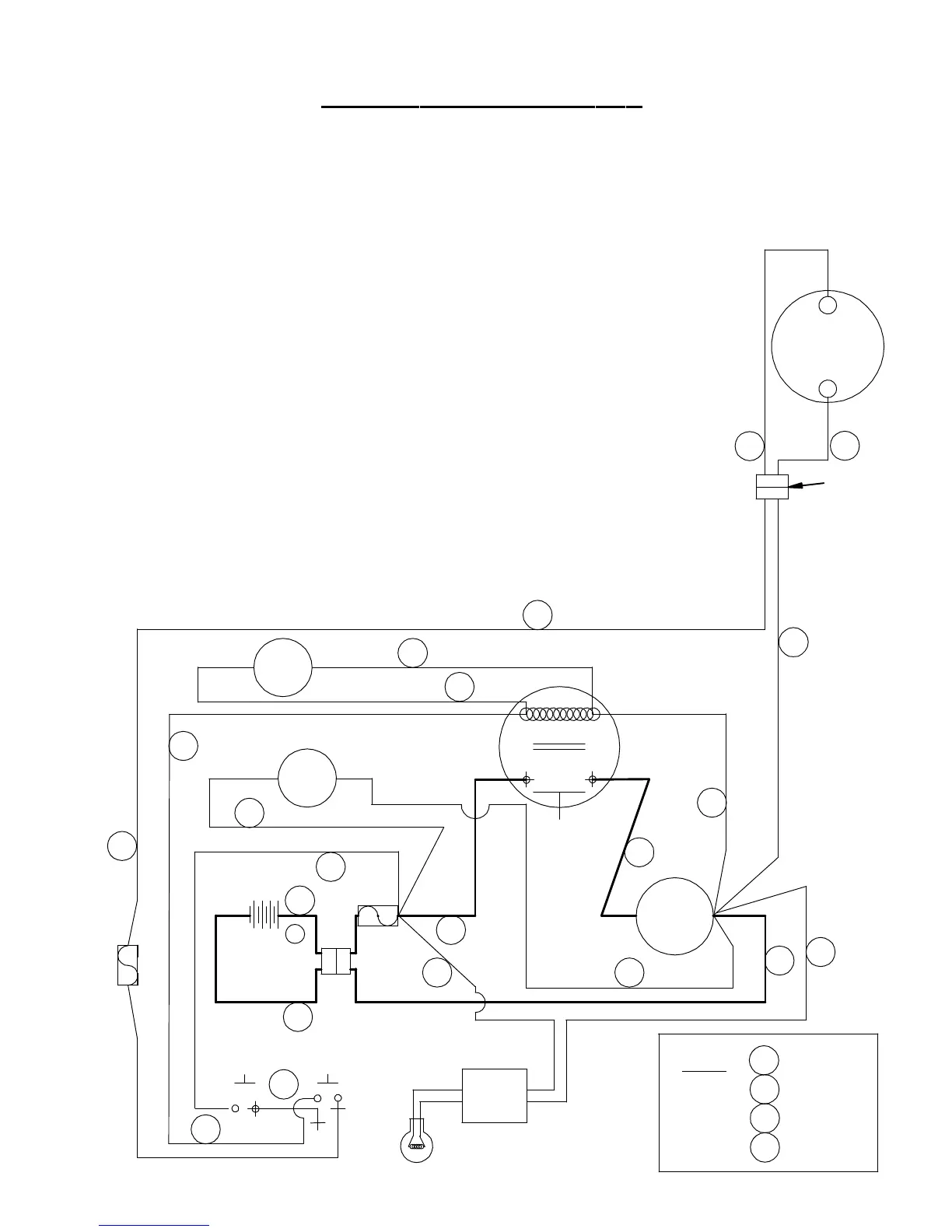
For machines after Serial No. "CI-3200" with
Single Electrical Switch for Main and Side Brooms
W
iring Schematics
B
R1
M1
M2
F1
F2
S1
S2
H
C
G
P
L
= Battery (12 Volt)
= Main Relay
= Main Broom Motor
= Side Broom Motor
= Side Broom Circuit Breaker (6 Amp)
= Main Circuit Breaker (80 Amp)
= Safety Switch
= Main and Side Broom Switch
= Hour Meter
= Battery Charger
= Grey 50 Connector
= Plug: Side Broom Harness
= Warning Light Unit
Wire
: = Red
= White
= Black
= Blue
R1
S1 S2
+
+
L
P
G
R
R
M2
B
B
B
B
B1
W
B1
R
R
R
M1
F1
R
B
W
G
F2
C
R
H
B
B1
W
R
R
B
-
B
R
B
PAGE 16B