Drwg. No.
4135
6
PLUS
10
GB
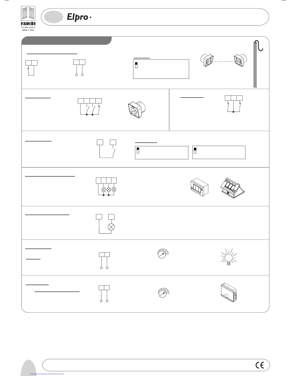
SINGLE- AND THREE-PHASE FOR SLIDING GATES
AND AUTOMATIONS FITTED WITH LIMIT SWITCHES
Photocells and Safety Edge:
PHOTOCELLS AND
SAFETY EDGE
12 13
24V (500 mA) OUTPUT (MAX. LOAD:
2 PAIRS PHOTOCELLS
1 RADIO RECEIVER)
Push Button Switch Pulin 3:
26
27
28
3
COMMON
Led to indicate status of Open - Stop -
Close switches
Electric lock:
Set the T4 Trimmer Time to the lowest value
The electric lock is excited for 2 seconds
1
DIP-SWITCH 1:
ON: Photocells stop gate while opening,
reverse it on closing once obstacle is
removed
OFF: Photocells do not stop gate while
opening, reverse it on closing in
case of an obstacle
Button switch:
3
4
5
6
STOP
COMMON
OPEN
CLOSE
Limit switch:
10
COMMON
8
9
LIMIT SWITCH
CLOSE
LIMIT SWITCH
OPEN
Radio Contact:
7
3
COMMON
RADIO
CONTACT
- Open/Close (Standard)
- Travel reversing on pulsing
- Step by step
2
5
ON: Step by step. Stop in between
OFF: Standard operating mode
ON: Gate is not reversed while opening
OFF: Any pulse reverses the gate
DIP-SWITCH 2 and 5 (NEVER set BOTH of them to ON at the same time):
24V 3W Indication Light:
Light ON = Open gate
Light OFF = Closed gate
Flashing (fast) 0.5s = Closing gate
Flashing (normally) 1s = Opening gate
Flashing (slowly) 2s = gate is stopped
3
11
Connect a 24VAC Modular Relay
(
T4 Trimmer Time from 2s to 255s)
to operate a 230V lamp
Courtesy light:
1
2
RS
RS
RS
RS
-
+
- TIME EXT (Electric lock and
courtesy light) from 2 to 255s
T4
-
+
T4
LOW VOLTAGE ELECTRICAL CONNECTIONS
®