vers. 1016
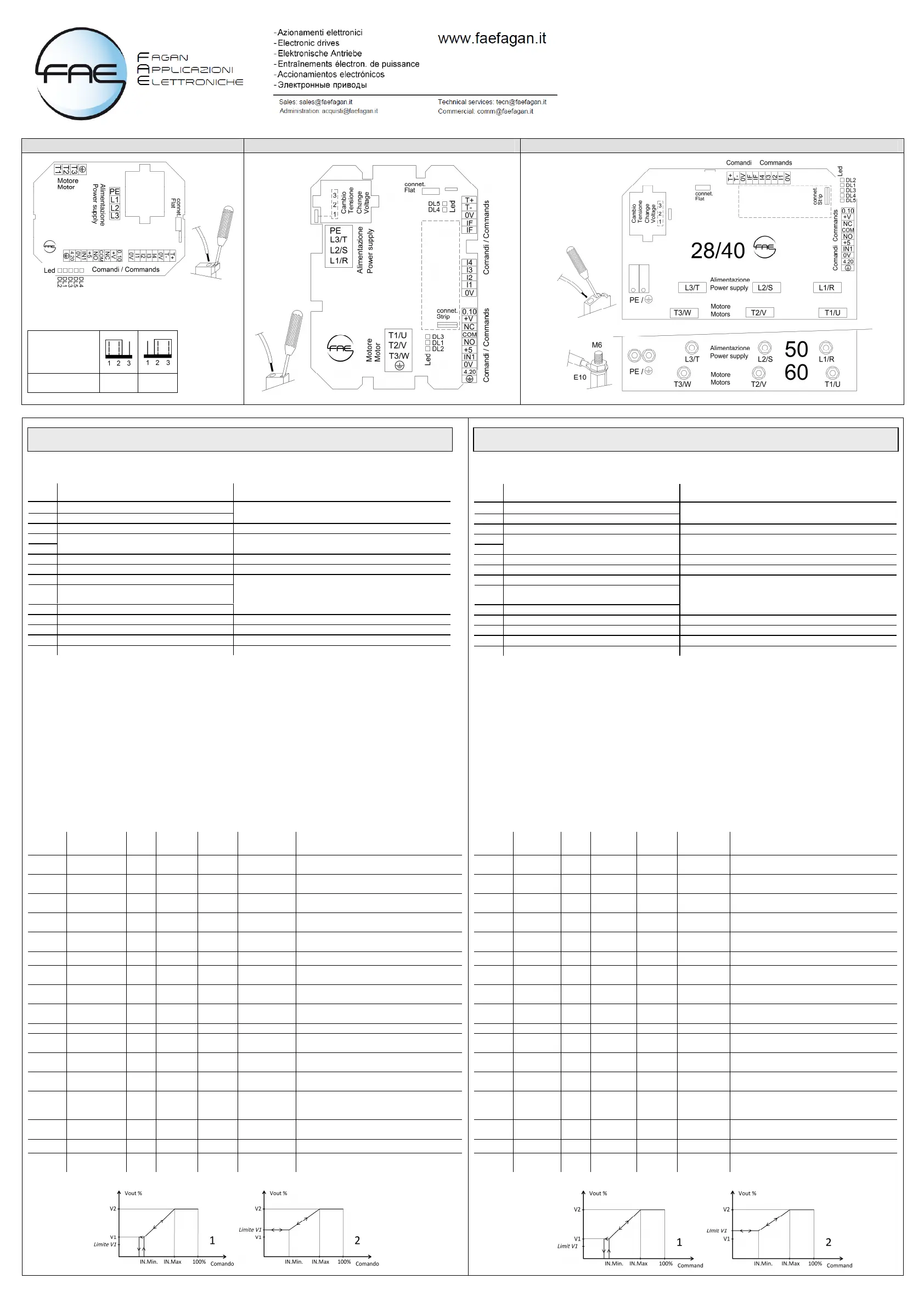
VRTS 8/10 vista scheda – view card VRTS 12/16/20 vista scheda – view card VRTS 28/40/50/60 vista scheda – view card
Cambio tensione
Change voltage
D = 440/460V
(not for VRTS8/10)
440 460
MORSETTIERA DEI COMANDI
SEGNALAZIONI LED
DL1 : giallo, inizia a lampeggiare al valore minimo del segnale di ingresso aumentando la sua frequenza man mano che aumenta il segnale
fino a restare acceso per segnale = 100%. Segue il segnale prioritario (vedi Impo. Base [IB] nel menù Parametri di Fabbrica).
DL2 : verde, acceso = presenza alimentazione.
DL3 : rosso, presenza allarme: 1 lampeggio = mancanza fase di alimentazione; 3 lampeggi = sovratemperatura interna; 5 lampeggi = Stop
per programmazione parametri;
DL4 : verde, lampeggia in trasmissione modbus.
DL5 : rosso, lampeggia in ricezione modbus.
INDIRIZZI MODBUS PRINCIPALI (Documentazione dettagliata su richiesta)
S* scrittura possible solo se il parametro “Blocco regolazione” è impostato a 1
S** reboot neccessario dopo la scrittura
Esempio: Richiesta del MASTER di lettura della variabile “uscita di tensione” identificato con indirizzo 0x0B: 01 03 00 0B 00 01
Richiesta del MASTER di scrittura sulla variabile “ingresso di comando Modbus” identificato con indirizzo 0x401: 01 06 04 01 00 01
Attenzione: Il comando di regolazione tramite modbus necessita di riscrittura nel relativo indirizzo entro il tempo di time out (default 30
secondi) anche se il valore rimane invariato. Scaduto il timeout, in mancanza di qualsiasi altro segnale di comando, il dispositivo
interromperà la regolazione spegnendo le uscite di potenza.
Descrizione Applicazione
T1 + Seriale RS485, Modbus RTU - slave
T1 - Seriale RS485, Modbus RTU - slave
Linea di collegamento seriale da un dispositivo che comanda
come Master
0V Massa I/O Massa I/O
IF
IF
Ingresso Pwm 2..20kHz (Ri = 500Ω, 5..24V)
Ingresso di comando a frequenza variabile
(solo su richiesta)
0.10 Ingresso analogico, tipo 0..10V (Ri = 40 kΩ) Ingresso di comando 0..10V
+V Uscita alimentazione 12V= (max 30mA) Alim. Potenziometro esterno per comando manuale
NC Uscita contatto norm. chiuso relè 1
COM
Uscita contatto comune relè 1
(1A-250V~/1A-30V=)
NO Uscita contatto norm. aperto relè 1
Uscita programmabile. Nella tipica configurazione per Difetto, il
relè è eccitato (NO-COM chiusi tra loro) e si diseccita se avviene
un’emergenza.
+5V Uscita alimentazione 5V= (max 15mA) /
IN 1 Ingresso pwm (5..15V, frequenza 100Hz) Ingresso di comando pwm a valore medio variabile
0V Massa I/O
Massa per ingresso analogico
4.20 Ingresso analogico, tipo 4…20mA (Ri = 100 Ω) Ingresso di comando 4..20mA
Indirizzo
HEX
Variabile Unità Lettura /
Scrittura
Valore
Min.
Valore
Max.
Descrizione
0x00B
Uscita di
tensione
% L - -
indica la percentuale di tensione erogata al
motore
0x00D Allarme Num L - -
0=nessun errore; 1=mancanza fase; 3=Temp
interna; 5=impostazioni errate
0x400
Blocco
regolazione
Num L/S 0 1
scrivere il valore 1 per abilitare la scrittura
Scrivere il valore 0 per riabilitare la regolazione
0x421
Indirizzo del
regolatore
Num L/S** 1 247 indica l'indirizzo modbus (slave) - default 0x01
0x422 Baudrate Num L/S** 1 3
(=1 se 9600bps); (=2 se 19200); (=3se 38400) -
default =2
0x423 Bit di stop Num L/S** 1 2 (=1 se 1 di stop); (=2 se 2 bit di stop) - default=1
0x424 Parità Num L/S** 1 3
(=1 se nessuna parità); (=2 per parità pari); (=3
per parità dispari) - default =1
0x425 Timeout sec L/S* 1 240
indica il tempo entro il quale il master deve
rinnovare il comando di regolazione
0x401
Comando via
Modbus
% L/S* 0 100
variabile che permette la regolazione (0-100)
tramite Modbus.
0x402 Ingresso min % L/S* 10 Ingresso max Segnale di comando tensione/velocita V1.
0x403 Ingresso max % L/S*
Ingresso
minimo
100 Segnale di comando tensione/velocita V2.
0x404
Tensione min.
V1
% L/S*
Lim.Min.
Motore
Tensione max.
V2
Tensione/velocita relativa al punto di segnale di
comando IN.MINIMO.
0x405
Tensione max.
V2
% L/S*
Tensione
min. V1
Lim. Max.
Motore
Tensione/velocita relativa al punto di segnale
comando IN.MASSIMO.
0x407 Reset Num L/S* 1 3
( =2 per resettare e caricare i valori di default del
regolatore) (=3 per riavviare dopo modifica
parametri dove è richiesto reboot)
0x40A
Lim. Velocità
V1
% L/S*
Lim Min.
Motore
Limite V2
Tensione che sostituisce V1, in modo Slave ,
quando LIMITE V1>V1.
0x411 Kick start Num L/S* 0 1 (=0 kick start disattivo)(=1 kick start attivo)
0x41E
Profilo di
regolazione
Num L/S* 1 2 (=1 curva lineare) (=2 curva per ventilatori assiali)
CONTROLS TERMINAL BOARD
LEDS WARNING SIGNALS
DL1 : yellow, starts to flash with input signal at minimum and increases the flashing frequency as the signal rises. It goes on steady with
signal = 100%. It follows the priority signal (see Basic Sett. [BS] in the Factory Parameters menu).
DL2 : green, steady ON = power supply ON.
DL3 : red, warning alarm ON: 1 flash = power phase lost; 2 flashes = external emergency; 3 flashes = internal over-temperature.
5 flashes = stop for parameters programming or error settings.
DL4 : green, flashing in modbus transmission.
DL5 : red, flashing in modbus reception.
MODBUS ADDRESS (Details available upon request)
S * Writing possible only if the parameter "Adjustment Lock" is set to 1
S ** necessary reebot after writing the changes
Example: Request by the MASTER to read the variable "output voltage" identified with address 0x0B: 01 03 00 0B 00 01
Request by the MASTER to write on the variable “Modbus input command” identified with address 0x401: 01 06 04 01 00 01
Caution: The regulation command via Modbus requires rewriting in its address within the time out (default 30 seconds) even if the
value remains unchanged. Over the time out, in absence of any other command signal, the regulator switch off the power outputs.
Description Application
T1 + Serial RS485, Modbus RTU - slave
T1 - Serial RS485, Modbus RTU - slave
Serial connection line to a Master controlled device
0V Ground I/O Ground I/O
IF
IF
Pwm input 2..20kHz (Ri = 500Ω, 5..24V) Variable frequency command input (only on request)
0.10 Analog input, tipo 0..10V (Ri = 40 kΩ) 0..10V analog command input
+V Aux. supply output 12V= (max 30mA) External potentiometer supply for manual command
NC Relay 1 contact output norm. closed
COM
Relay 1 common contact output
(1A-250V~/1A-30V=)
NO Relay 1 contact output norm. open
Programmable output. With standard setting for Defect, the relay
is enabled (NO-COM eachother closed) and is disabled in
emergency case.
+5V Output aux. supply 5V= (max 15mA) /
IN 1 Analog input pwm (5..15V, 100Hz frequency) Pwm input command with variable average value
0V Ground I/O
Ground for analgical input
4.20 Analog input , type 4…20mA (Ri = 100 Ω) 4..20mA analog command input
HEX
Address
Variable Unit Reading /
Writing
Min.
Value
Max.
Value
Description
0x00B
Voltage
output
% R - -
Indicates the output percentage voltage/speed.
0x00D Allarm Num R - -
0=no error; 1=phase lost; 3=over temperature;
5=incorrect settings
0x400
Stop
regulation
Num R/W 0 1
Write the value 1 to enable writing and disable
the running. Place to 0 to re-enable the running.
0x421
Regulator
address
Num R/W** 1 247
Indicates the modbus address (slave) - default
0x01
0x422 Baudrate Num R/W** 1 3
(=1 if 9600bps); (=2 if 19200); (=3 if 38400) -
default =2
0x423 Stop Bit Num R/W** 1 2 (=1 if 1 stop bit); (=2 if 2 stop bit) - default=1
0x424
Parity
Num R/W** 1 3
(=1 if no parity); (=2 if even parity); (=3 if odd
parity) - default =1
0x425 Timeout sec R/W* 1 240
Indicates the time within which
the master must renew his command regulation
0x401
Command
by Modbus
% R/W* 0 100
variable for command the regulation (0-100) by
Modbus
0x402 Min. input % R/W* 10 Max input Voltage signal command/speed V1
0x403 Max input % R/W*
Min.
input
100 Voltage signal command/speed V2
0x404
Min. V1
Voltage
% R/W*
Lim.Min.
Motor
Max. V2
Voltage
Voltage/speed of IN.MIN. command signal point
0x405
Max. V2
Voltage
% R/W*
Min. V1
Voltage
Lim. Max.
Motor
Voltage/speed of IN.MAX. command signal point
0x407 Reset Num R/W* 1 3
(=2 to reset and load the controller’s default
values) (=3 to restart the regulator after changing
the parameter/s when is required the reboot)
0x40A
Lim. Spped
V1
% R/W*
Lim.Min.
Motor
V2 Limit Voltage that replaces V1, when V1 LIMIT>V1.
0x411 Kick start Num R/W* 0 1 (=0 kick start enable)(=1 kick start able)
0x41E
Regulation
profile
Num R/W* 1 2 (=1 linear profile) (=2 axial fans profile)
 Loading...