These instructions are presented in step by step sequence. Attach a template with tape to your door and frame as an aid to
prepare for device mounting.
Please read instructions thoroughly before installation.
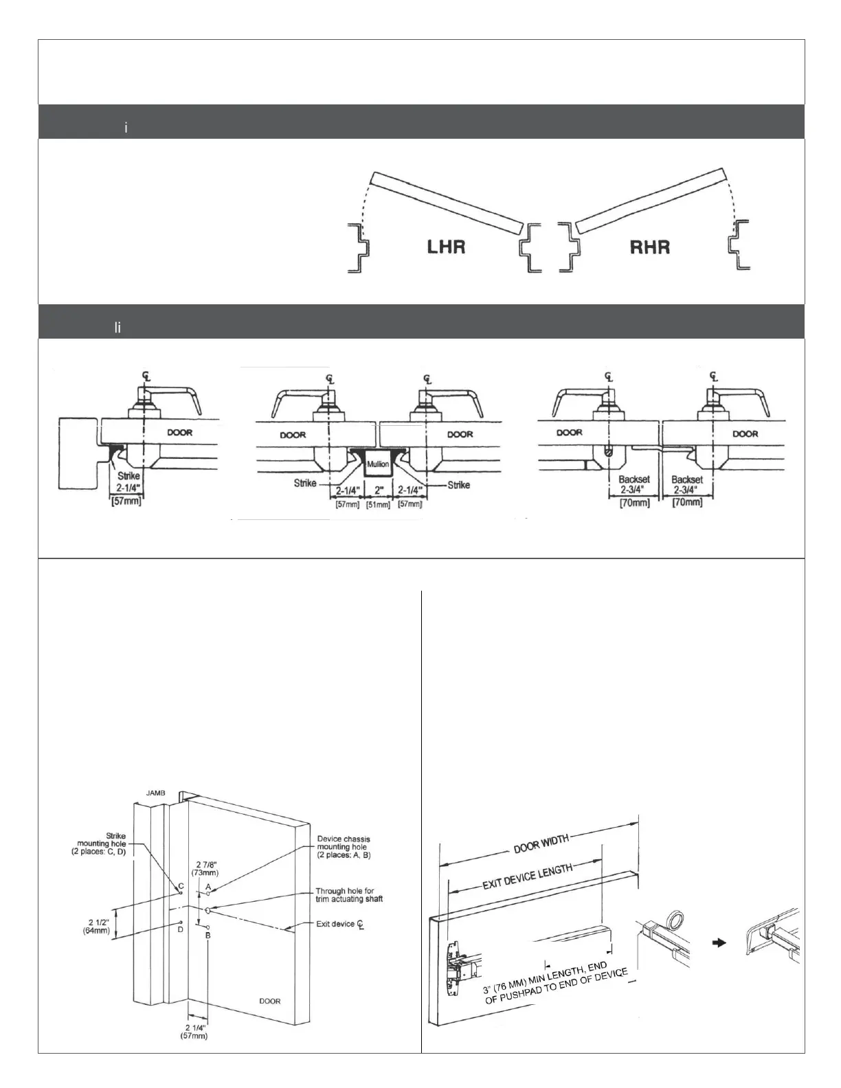
Use this diagram to determine the hand of the door.
Outside of door
Inside of door
Single Door Double Door with Mullion Double Door without Mullion
One rim exit device Two rim exit devices with mullion Rim exit device and surface vertical rod
exit device combination
Mark and drill mounting holes.
a.
Mark centerline of exit device by marking a line across
the door and stop 40" (101.6 cm) above finished floor as
shown.
b.
Apply template to the door and align centerlines on
template with centerlines on door. Mark location of two (2)
exit device mounting holes as shown on template.
c.
Move template against door stop. Mark two (2) mounting
holes for strike holes for panic device, or three (3) holes for
a fire rated device.
d.
Drill holes.
Measure and cut device to length.
The exit device has two size options, one for a 36" (91.4 cm) door
width and one for a 48" (122 cm) door width.
For 36" or 48" door width, no cutting is required. Skip to next step.
a.
Measure door opening (door width).
b.
Measure exit device length NOT INCLUDING end cap.
c.
Exit device length must be 4" (102 mm) shorter than door
width.
d.
If necessary, cut the exit device to appropriate length.
• Be sure the end of device body and cover plate are flush
before cutting.
• Device must be cut square for proper end cap fit.
To cut device:
 Loading...