EasyManua.ls Logo

Falcon SC71 User Manual

Falcon SC71
5 pages
To Next Page IconTo Next Page
Page #1 background imageLoading...
Page #1 background image
1
Door and Frame Preparation:
A. Choose degree of door opening.
B. Drill per appropriate fastener, using chart above.
2¹⁄₂"
(64 mm)
2³⁄₈"
(60 mm)
6³⁄₄"
(171 mm)
A
C
L
Hinge
¹¹⁄₁₆"
17 mm
B
⁵⁄₁₆"
8 mm
1³⁄₄"
44 mm
1¹¹⁄₁₆"
43 mm
3³⁄₈"
86 mm
1¹⁄₁₆"
27 mm
2¹⁄₈"
54 mm
C
L
Hinge
Top View
Right Hand Door Illustrated. Same dimensions
apply for Left Hand Door measured from center
line of hinge.
Opening A B
Up To 100°
8C\v" (222 mm) 10B\," (270 mm)
101° – 130°
7Z\v" (184 mm) 9Z\," (232 mm)
131° – 150°
6Z\v" (159 mm) 8Z\," (206 mm)
151° – 180°
5Z\v" (133 mm) 7Z\," (181 mm)
Front View
Fasteners Use Description Drill/Tap
Closer Body #14 Wood 1/8" Drill
1/4-20 #7 Drill, 1/4-20 Tap
Arm Shoe #14 Wood 1/8" Drill
1/4-20 #7 Drill, 1/4-20 Tap
Thru-bolt Wood/Metal 3/8" Drill
Fifth Hole
Spacer
#14 Wood 1/8" Drill
1/4-20 #7 Drill, 1/4-20 Tap
Arm
Attachment
Arm
Attachment
Lock Washer
Cover Plug
Cover Screw
Closer mounted on push
side of door
(opposite of hinge side).
CAUTION
Improper installation or regulation may result in personal
injury or property damage. Follow all instructions
carefully. For questions, call Falcon at number below.
L=Latch Speed Valve
S/D=Main Speed Valve
B=Backcheck Valve
Spring Power Adjustment
SC71
L=Latch Speed Valve
S=Main Speed Valve
S/D=Delay Action Valve
Spring Power Adjustment
SC71 DEL
SC71 Series Closer
Installation Instructions
Forged Arm Models, SC71 (1-6 Adj.)
"P" Valve, Normally Closed
(877) 671-7011
Question and Answer IconNeed help?

Do you have a question about the Falcon SC71 and is the answer not in the manual?

Falcon SC71 Specifications

General IconGeneral
BrandFalcon
ModelSC71
CategoryDoor Opening System
LanguageEnglish

Summary

Door and Frame Preparation

Choose Degree of Door Opening

Select the desired door opening angle based on provided charts.

Drill per Appropriate Fastener

Drill holes according to the fastener type and chart specifications.

Determine Door Width and Spring Power

Adjust Spring Power to Match Chart

Match door width to the correct spring power setting using the provided chart.

Install Closer Components

Install Arm and Shoe Assembly

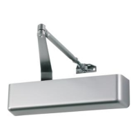
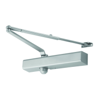
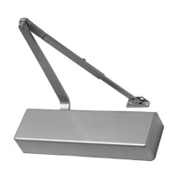
Install the arm and shoe assembly onto the door frame.

Install Closer Onto Door

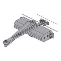
Mount the closer body onto the door, noting valve orientation.

Attach Main Arm to Closer

Connect the main arm to the closer body at a 45-degree angle.

Adjustment and Cover Installation

Adjustment Instructions

Adjust latch speed, main speed, and backcheck using designated valves.

Attach Cover with Screws

Secure the closer cover using screws and insert cover plugs.

Adjust Optional Handed Hold-Open Arm

Loosen and tighten the hold-open nut for proper operation.

Related product manuals