FALCON F
+ USER MANUAL
DCI DigiGuide 10.31.2022
DIGITAL CONTROL, INC 7
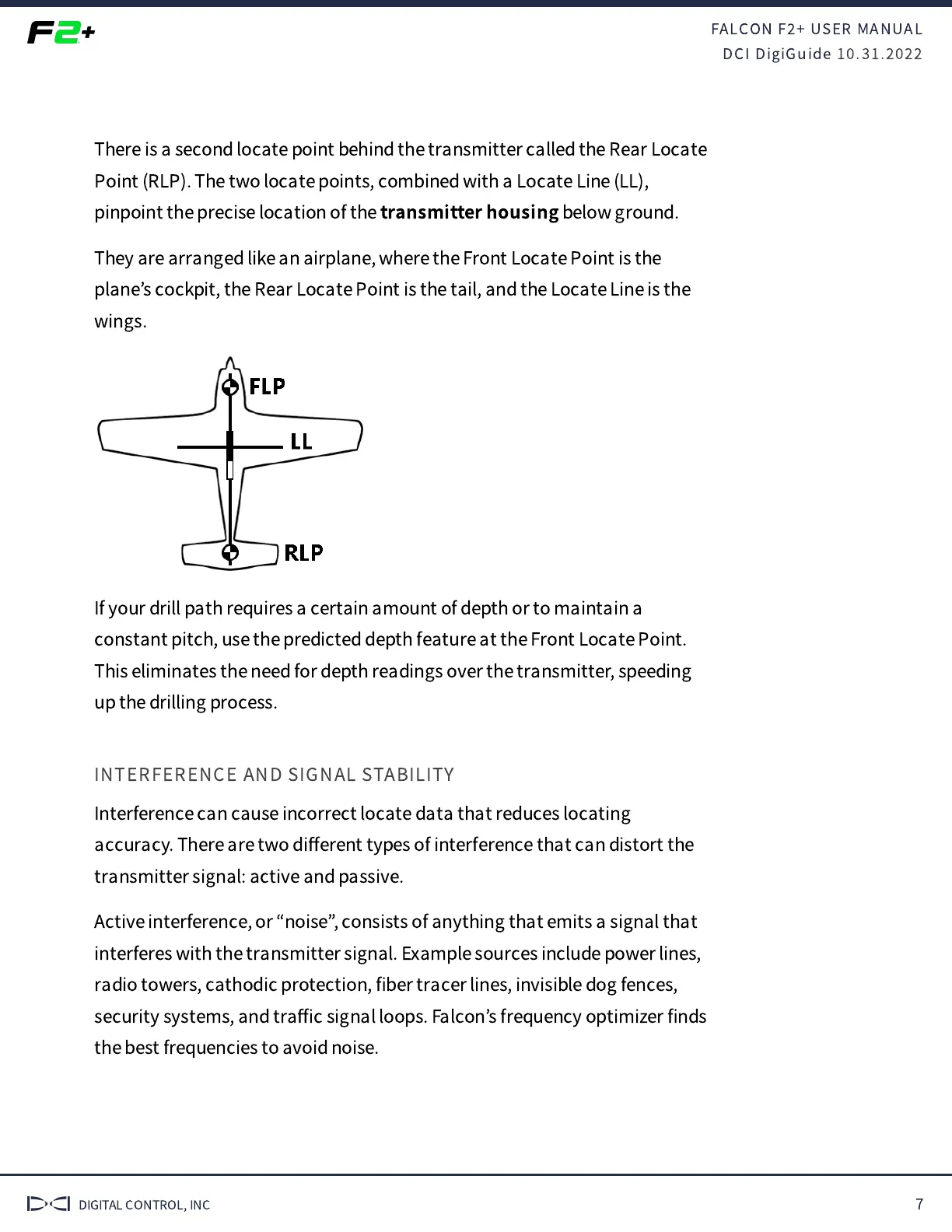
There is a second locate point behind the transmitter called the Rear Locate
Point (RLP). The two locate points, combined with a Locate Line (LL),
pinpoint the precise location of the
transmitter housing
below ground.
They are arranged like an airplane, where the Front Locate Point is the
plane
’
s cockpit, the Rear Locate Point is the tail, and the Locate Line is the
wings.
If your drill path requires a certain amount of depth or to maintain a
constant pitch, use the predicted depth feature at the Front Locate Point.
This eliminates the need for depth readings over the transmitter, speeding
up the drilling process.
INTERFERENCE AND SIGNAL STABILITY
Interference can cause incorrect locate data that reduces locating
accuracy. There are two di
ff
erent types of interference that can distort the
transmitter signal: active and passive.
Active interference, or
“
noise
”
, consists of anything that emits a signal that
interferes with the transmitter signal. Example sources include power lines,
radio towers, cathodic protection,
fi
ber tracer lines, invisible dog fences,
security systems, and tra
ffi
c signal loops. Falcon
’
s frequency optimizer
fi
nds
the best frequencies to avoid noise.
 Loading...