EasyManua.ls Logo

Falcon LA Series User Manual

Falcon LA Series
7 pages
To Next Page IconTo Next Page
Page #1 background imageLoading...
Page #1 background image
LA1000-V-EO
LA1000-V-F-EO
Serie LA
LA Series
Barra Antipánico / Cortafuego
PRINCIPALES COMPONENTES
NAME OF MAIN PARTS
Instrucciones de instalación
Installation Instructions
Top strike
Strike superior
Top latch
Pestillo superior
Top latch assembly
Mecanismo del
pestillo superior
Mounting bracket
Placa de montaje
Top latch assembly cover
Cubierta del
pestillo superior
Rod guide
Guía de las barras
Mechanism housing
Mecanismo
Dogging device
(Fire Exit Hardware does
not come with this device)
Mecanismo de dogging
(Los dispositivos cortafuego
no incluyen este sistema)
End cap bracket
Placa de montaje
posterior
End cap
Cubierta posterior
Top rod
Barra superior
Rod connector
Conector de
la barra
Rod connector
Conector de
la barra
Chassis assembly
Ensamble del chasis
Chassis
Chasis
Bottom rod
Barra inferior
Top strike
Strike superior
Bottom latch
Pestillo inferior
Bottom latch assembly
Mecanismo del
pestillo inferior
Mounting bracket
Placa de montaje
Bottom latch assembly cover
Cubierta del
pestillo inferior
Push bar
Barra push
1
Question and Answer IconNeed help?

Do you have a question about the Falcon LA Series and is the answer not in the manual?

Falcon LA Series Specifications

General IconGeneral
CategoryRacks & Stands
Adjustable HeightNo
ColorBlack
MaterialSteel
Wheel TypeCaster wheels

Summary

Main Components Overview

Prepare the Door for Installation

Door Hole Marking and Drilling

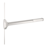
Mark and drill all holes on the door for device chassis, latches, and end cap bracket.

Install Mounting Brackets, Device, and Exterior Trim

Bracket and Device Mounting

Install mounting brackets, device chassis, and end cap bracket, ensuring proper alignment and levelness.

Trim Actuating Shaft Connection

Ensure trim actuating shaft inserts into the device cam and rod connector.

Install Bottom Rod and Bottom Strike

Bottom Latch Assembly and Rod Attachment

Mount bottom latch assembly into bracket and screw threaded end of bottom rod to it.

Install Top Rod and Top Strike

Bottom Rod Securing and Strike Plate Installation

Secure bottom rod with glide plate and install bottom strike into the finished floor.

Installation Functionality Check

Test push bar operation for proper latch retraction and extension.

Top Rod Measurement, Cutting, and Connection

Top Rod Length Measurement and Cutting

Measure and cut the top rod length to the edge of the rod connector.

Rod Connector and Setting Screw Installation

Insert rod connector into the non-threaded end of top rod and fasten the setting screw.

Top Rod Securing to Glide Plate

Secure the top rod with the rod connector to the upper glide plate.

Test Device Operation

Latch and Door Operation Test

Test push bar, latch retraction/extension, and door opening/closing.

Install Covers and Guides

Cover and Rod Guide Installation

Install chassis cover, end cap, latch covers, and two rod guides.

Door Handing Identification

Dogging Device Operation

Engaging and Disengaging Dogging

Press push bar and turn dogging wrench 90° clockwise to engage, counter-clockwise to disengage.