4
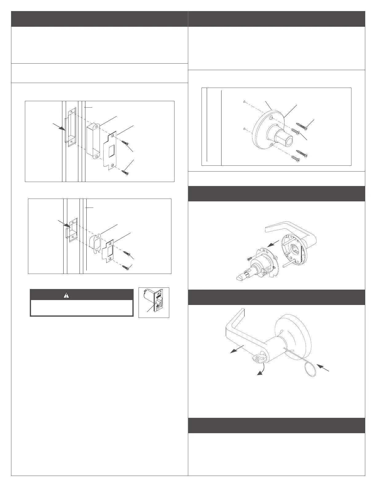
6 Prepare the door jamb and install the strike.
When installing on a wood door jamb, complete steps
6a and 6b:
6a Center the strike opening over 1" (25 mm) hole in jamb.
Then, trace the outline around the strike on the door jamb.
6b Mortise the door jamb to accommodate the strike dust box
and the strike faceplate.
6c Insert the strike box if required and fasten the strike to the
jamb with appropriate screws as shown.
ANSI dust box
Mortise for
dust box
and strike
#12 combination
screws
ANSI strike
faceplate
Jamb
ANSI strike (standard)
Dust box
Mortise for
dust box
and strike
#8 combination
screws
T strike
faceplate
Jamb
T strike (optional)
CAUTION
Deadlocking plunger of the latchbolt must
not enter the opening in the strike plate.
Plunger
L Note: When the strike box is not used, the recess in the jamb
must be a minimum of >\zn" (14 mm) deep to allow the latchbolt
to extend to its full projection.
7 Install single dummy (T12) trim.
7a Using the template described at step A, locate and mark the
center for two (2) mounting holes.
Wood doors: Drill two (2) pilot holes B\cx" (4 mm) x M\," (22 mm)
deep for #12 wood screws.
Metal doors: Drill and tap two (2) holes for #12-24 machine screws.
7b Secure the inside trim/spindle assembly to the door with the
appropriate screws.
Inside trim
assembly
Inside of
door
#12-24 x C\v"
screws (metal)
Groove
#12 x 1Z\x"
screws (wood)
7c See step 5 for rose and lever installation.
Remove keyed lever trim
Remove outside trim retaining screw and slide the outside trim
from the chassis.
Remove cylinder levers except IC cylinder levers
60°
a
b
c
a. Insert the key and rotate clockwise approximately 60°.
b. Depress lever retainer with pin wrench.
c. Slide lever o spindle.
Reinstall cylinder levers (except IC)
• Insert cylinder into spindle.
• Slide lever onto spindle and push on over the lever retainer.
• Insert key into cylinder and rotate clockwise approximately
60° and push lever over retainer.
• Pull on the lever to be sure the lever retainer is engaged.
 Loading...