EasyManua.ls Logo

Faller HALF-TIMBERED HOUSE User Manual

Faller HALF-TIMBERED HOUSE
12 pages
To Next Page IconTo Next Page
Page #1 background imageLoading...
Page #1 background image
Vor Beginn des Bastelns sollten Sie sich mit den Spritzlingen und der Anleitung vertraut machen.
Sollte es einmal vorkommen, dass ein Teil im Bausatz fehlt, kreuzen Sie bitte das fehlende Teil in
der Anleitung an und schicken Sie diese bitte an Fa. Gebr. FALLER GmbH, Abt. Kundendienst,
Kreuzstraße 9, 78148 Gütenbach. Sie erhalten dann umgehend Ersatz.
In diesem Bausatz sind einige Kunststoffteile übrig.
Before commencing with the assembly please familiarize yourself with the parts and read the
instructions carefully.
In case of missing parts please indicate these on the instructions leaflet with a circle and return
the leaflet to Gebr. FALLER GmbH, Kreuzstraße 9, D-78148 Gütenbach, Germany.
You will receive the replacement by return.
Some of the parts in this box are not needed to construct the model.
Avant de commencer le montage de votre maquette bien lire la notice et repérer les grappes.
Si une pièce manquait dans une boîte, cochez la pièce correspondante sur la notice et renvoyez
la nous à Gebr. FALLER GmbH, Kreuzstraße 9, D-78148 Gütenbach (R.F.A.).
Nous vous ferons parvenir la pièce par retour.
Dans cette boîte se trouvent quelques pièces qui ne seront pas utilisée pour le montage.
Vóór het bouwen zou men de gietstukken en de handleiding moeten bestuderen.
Indien onverhoopt een onderdeel aan het bouwpakket ontbreekt, gelieve men het ontbrekende
deel in de handleiding aan te kruisen en deze te zenden aan Gebr. FALLER GmbH, Kreuz-
straße 9, D-78148 Gütenbach. U ontvangt dan omgaand en gratis het ontbrekende onderdeel.
Van dit bouwpakket worden enkele kunststof delen niet gebruikt.
D
F
GB
NL
170688
Spezial-Seitenschneider
zum gratfreien Abtrennen von
feinsten Spritzteilen.
Nur für Polystyrol geeignet.
Special side cutter
for cutting off ultra-fine moulded
parts without burrs.
Only suitable for polystyrene.
Pince coupante spéciale
pour couper sans bavure les
pièces miniatures moulées par
injection.
Uniquement appropriée pour le
polystyrène.
Speciale zijkniptang
voor het braamloos afknippen
van de fijnste gietstukdelen.
Alleen geschikt voor polystyrol.
170492
FALLER-EXPERT
Flüssigkleber in Plastikflasche mit
Spezialkanüle für feinste Klebstoff-
dosierung.
FALLER-EXPERT
Liquid cement in plastic bottle with
canule for very fine dosage.
FALLER-EXPERT
Colle liquide en bouteille plastique
avec bec verseur pour un dosage
précis.
FALLER-EXPERT
Vloeibare lijm in plastic-flacon met
doseerbuisje om nauwkeurig te
lijmen.
Sa. Nr. 226 831 2
Fachwerkhaus
Half-timbered house
Maison à pans de bois
Vakwerkhuis
Art. Nr. 232339
Stromverbrauch:
Current consumption:
Consummation de courant:
Stroomverbruik:
1 x 55 mA
Art.180670
Inhalt Spritzlinge
Contents Sprues
Contenu Moulages
Inhoud Gietstukken
8A
1
x
8B
1
x
8D
1
x
9
1
x
10
1
x
11
1
x
12
1
x
14
1
x
15A
1
x
15B
1
x
16A
1
x
16B
1
x

Other manuals for Faller HALF-TIMBERED HOUSE

Question and Answer IconNeed help?

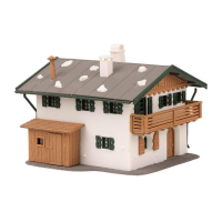
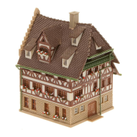
Do you have a question about the Faller HALF-TIMBERED HOUSE and is the answer not in the manual?

Faller HALF-TIMBERED HOUSE Specifications

General IconGeneral
BrandFaller
ModelHALF-TIMBERED HOUSE
CategoryToy
LanguageEnglish

Summary

Building Component Identification

Section A: Wall Components

Diagram showing wall sections with part numbers 15/15, 15/10, 15/4.

Section B: Base and Window Elements

Diagram showing base parts and window elements with part number 16/26.

Section C: Wall Details

Diagram showing wall sections with circular and rectangular openings, part 16/28.

Section D: Wall with Openings

Diagram showing wall sections with openings and part number 16/28.

Section E: Front Facade Elements

Diagram showing facade elements with windows and door, parts 16/27, 16/26, 16/1.

Section F: Window Panels

Diagram showing window panel sections with part numbers 16/27, 16/26.

Section G: Wall Section with Windows

Diagram showing wall section with multiple windows, parts 15/2, 15/13, 15/9, 15/11.

Section H: Doorway and Window Sections

Diagram showing doorway and window sections, parts 16/28, 16/2, 16/27.

Section I: Main Building Assembly

Diagram showing the main building structure with wall sections and part number 14/1.

Assembly Steps - Part 1

Section J: Gable and Wall Assembly

Diagrams for assembling gable and wall sections with parts 10/2, 9/1, 10/5.

Section K: Main House Facade

Diagrams for assembling the main house facade with parts 8/19, 8/22.

Section L: Upper Facade Assembly

Diagrams for assembling the upper facade with parts 8/38, 8/36.

Section M: Wall Panel with Door

Diagrams for assembling a wall panel with a door, parts 10/6, 9/5.

Section N: Window and Wall Sections

Diagrams showing window and wall sections, parts 8/22, 8/36.

Section O: Window Panel Detail

Diagram showing a window panel with part numbers 8/22, 8/36.

Section P: Wall Section with Windows

Diagrams for assembling a wall section with windows, parts 10/4, 9/3.

Section Q: Lower Facade Assembly

Diagrams for assembling lower facade sections with windows, part 8/22.

Section R: Ground Floor Assembly

Diagrams for assembling ground floor sections with windows, part 8/36.

Assembly Steps - Part 2

Section S: Base Plate Assembly

Diagrams for assembling base plates with parts 16/14, 16/13.

Section T: Roof Support Assembly

Diagrams for assembling roof support structures with parts 16/9, 16/6.

Section U: Main Building Structure

View of the partially assembled main building structure with labels U, I, T, S.

Section V: Wall and Roof Integration

Diagrams for integrating wall and roof elements with part 10/1.

Section W: Upper Floor Assembly

Diagrams for assembling the upper floor sections with parts 8/19, 8/18, 8/35.

Section X: Gable and Wall Connection

Diagrams for connecting gable and wall elements with parts 8/38, 11/31, 8/37.

Assembly Steps - Part 3

Section a: Gable Wall Element

Diagram showing a gable wall element with parts 10/11, 9/7.

Section b: Wall with Windows

Diagram showing a wall section with windows, part 8/18.

Section c: Window Panel Attachment

Diagram showing attachment of window panels with part 8/37.

Section d: Window Detail

Diagram showing a window detail with parts 8/22, 10/12.

Section e: Main Structure Assembly

View of the main structure assembly with labels c, d, e, 15/12, U.

Assembly Steps - Part 4

Section f: Main Building Integration

View of the integrated main building with labels f, e, 16/30.

Section g: Roof Support Frame

Diagrams showing roof support frames with parts 16/15, 16/16, 16/24, 16/23, 16/22.

Section h: Base Tray Assembly

Diagram showing a base tray assembly with part 14/3.

Section i: Wall with Door Panels

Diagrams showing wall sections with doors, parts 10/9, 9/4.

Section j: Door and Wall Sections

Diagrams showing door and wall sections, parts 10/7, 9/6.

Section k: Roof and Wall Connection

Diagrams showing roof and wall connections with parts 10/3, 10/8, 9/8.

Section l: Gable and Window Assembly

Diagrams showing gable and window assembly with part 8/17, 8/22.

Section m: Facade with Windows

Diagrams showing facade sections with windows, part 8/36.

Section n: House Entrance Assembly

Diagrams showing house entrance assembly with parts 8/22, 8/36.

Assembly Steps - Part 5

Section o: Tower Integration

Diagram showing integration of tower elements with labels o, h, f.

Section p: Roof Frame Components

Diagrams showing roof frame components with parts 16/5, 15/20.

Section q: Roof Detail Pieces

Diagrams showing roof detail pieces with parts 16/3.

Section r: Window Masking Paper

Diagrams showing window masking paper with parts 16/29, 15/22.

Section s: Wall Detail Pieces

Diagrams showing wall detail pieces with parts 16/4, 15/21.

Section t: Window Panel and Door

Diagrams showing window panel and door elements with labels t, r.

Section u: Ground Cover Assembly

Diagrams showing ground cover assembly with labels u, t.

Section v: Final Building Assembly

View of the final building assembly with labels v, u, 11/12.

Decorative Elements and Roof Assembly

Section A: Roof Tile Components

Diagrams showing roof tile components and quantities with parts 8/21, 11/5.

Section B: Decorative Element 1

Diagrams showing decorative element 1 with parts 11/7, 11/6.

Section C: Decorative Element 1 Assembly

Diagrams showing assembly of decorative element 1 with parts 11/7, 11/6.

Section D: Roof Structure Components

Diagrams showing roof structure components with parts 8/20, 11/4.

Section E: Decorative Element 2

Diagrams showing decorative element 2 with parts 11/7, 11/6.

Section F: Decorative Element 2 Assembly

Diagrams showing assembly of decorative element 2 with parts 11/7, 11/6.

Section G: Roof Section Assembly

Diagrams showing roof section assembly with parts 12/6, 12/5, 12/2.

Section H: Roof Base Assembly

Diagrams showing roof base assembly with parts 12/5, 12/6, 12/1.

Section W: Building with Roof Details

View of the building with integrated roof details and labels W, V, 16/8, 16/7.

Roof Detailing and Final Assembly

Section G: Assembled House View 1

View of the assembled house with label G.

Section H: Assembled House View 2

View of the assembled house with label H.

Section I: Main Structure Assembly

View of the main structure assembly with labels I, W.

Section J: Roof and Dormer Integration

Diagrams showing roof and dormer integration with parts 11/3, 11/9, 11/8, 12/4, 12/3, 12/8, 11/1.

Main House Assembly Details

Section K: House Facade and Roof

View of the house facade and roof with label K.

Section J: Building Assembly Detail

Detailed view of building assembly with labels J, 15/12.

Section L: House Exterior Assembly

View of the house exterior assembly with labels L, K.

Final Assembly and Detailing

Section M: Tower Assembly

Diagrams showing tower assembly with parts 9/10, 9/9, 9/12.

Section N: Tower and Wall Integration

Diagrams showing tower and wall integration with parts 9/11.

Section O: Building with Gutter

View of the building with gutter system and labels O, 14/7, L, 14/5.

Section P: Final House Assembly

View of the final house assembly with labels P, O, 11/27, 11/28.

Accessory Assembly and Final Touches

Section Q: Small Structure Assembly

Diagrams for assembling small structures with parts 11/22, 11/23, 11/20.

Section R: Birdhouse Assembly

Diagrams for assembling a birdhouse with parts 11/24, 11/21.

Section S: Birdhouse Detail

View of the assembled birdhouse with label S.

Section T: Final Building View

View of the final building assembly with labels T, S, 11/27, 11/28, P.

Related product manuals