Do you have a question about the F&S Bondtec 56 i Series and is the answer not in the manual?
Defines the applicability scope and limitations of this user manual for the bonding system.
Outlines terms, conditions, and exclusions for guarantee, warranty, and liability claims.
Details limitations and warnings regarding connecting the machine to a network during operation.
Lists the components and additional information included in the entire documentation package.
Emphasizes the importance of reading and understanding the user manual for safe operation.
Provides essential safety guidelines and warnings for operating the bonding machine.
Confirms the machine's compliance with CE standards and its attached declaration.
Specifies that the bonder is exclusively approved for bonding applications.
States that the manufacturer is not aware of any misuse cases.
Details potential hazards like moving parts, hazardous substances, and hot surfaces.
Outlines the proper installation of guards and PPE requirements for machine operation.
Covers emergency behavior, staff qualification, and safe disposal procedures for the machine.
Provides detailed dimensions, weight, required free space, and table size for the machine.
Specifies the X, Y, and Z axis travel ranges within the bonding area.
Details ambient temperature, humidity, noise levels, and required electrical/air connections.
Lists specifications for the 5610i and 5630i bondheads, including wire diameter and bond strength.
Defines substrate types and bonding wires as specified in the purchase agreement.
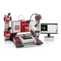
Identifies key components of the bonding machine, including Bondhead, Microscope, and controls.
Describes the main switch, emergency stop, monitor, joystick, and other user interface controls.
Explains the Cartesian coordinate system (X, Y, Z axes) and zero positions for machine movement.
Defines components and functions of various bond heads, including wire spool holder and transducer.
Provides instructions for secure transport and packaging of the machine and bond heads.
Specifies environmental conditions and precautions for storing the machine to prevent damage.
Outlines requirements for installing the machine, including accessibility and table stability.
Details essential steps before commissioning, including safety checks and unpacking.
Explains how to connect the bonder to the power supply safely and correctly.
Details how to connect the bonder to the vacuum network via the specified socket.
Describes how to connect the ultrasonic generator, including data connection types (USB/RS232).
Details the main menu, toolbar, and specific functions like Live Video and Plot Program.
Explains manual axis movement, wire clamping, wire feed, and device clamping operations.
Describes common operations and toolbar icons used for frequent tasks.
Guides users through creating a new bond program, including basic settings and parameter loading.
Details how to define further influencing bond process parameters under Global Settings.
Details the process of bonding a single wire, including teaching bond positions and measuring height.
Explains the Step Mode for analyzing and observing the bond process in individual steps.
Guides on setting critical parameters like Total Bond Time, US Power, Bond Force, and Touchdown Steps.
Guides setting bonding time based on wire diameter for optimal adhesion and weld shape.
Explains how US Power affects oscillation and weld strength, including US Burst functionality.
Details bond force dependency on wire diameter and includes activation of Bondforce Ramp.
Explains the role of TD Steps in deforming the wire and setting Z-axis movement.
Describes displaying and setting deformation limits to automatically stop the machine.
Allows selection between Standard and Expert loops, detailing motion sequences and geometries.
Provides basic settings for Standard Loop at Wedge-Wedge and Ball-Wedge, including loop height and presign.
Details Expert Loop options like Reverse 3, U-Turn, and Loopheight Compensation.
Explains wire cutting methods for thin and thick wires, including knife adjustment.
Guides on teaching chip positions, defining reference points, and setting light/camera for pattern recognition.
Details teaching bond positions for wires using the Learn Wire function and saving coordinates.
Explains duplicating modules using Repeat Module and Module Matrix for efficient programming.
Restores program positions as if trained at the current position; useful for changing PRU positions.
Describes how to measure missing chip heights when component geometry prevents it in Learn Chip.
Allows moving the entire program by an offset, useful after part holder changes.
Visualizes the bond program for orientation and complex changes, enabling zooming and navigation.
Enables changing parameters for multiple selected wires simultaneously via the plot program.
Allows loading or saving parameters for selected wires from single wire mode or a library.
Enables copying whole chips or single wires, with individual offset teaching and rotation.
Automates duplication of multiple wires with a single XY offset, ideal for repetitive sequences.
Allows moving selected subareas, wires, or bond points by teaching a new position.
Ideal for duplicating single wires with separate XY offsets for each bond position.
Allows changing the order of bonds, visualizing changes in the Plot Program.
Covers starting automatic processing, manual adjustment, and stopping the process.
Explains using rebond mode for adhesion issues or repairs, with temporary coordinate storage.
Discards last adjustment data, allowing a new adjustment process to be performed.
Monitors bond quality using Deformation Limit Control and Wedge Counter, with reset options.
Guides on using pattern recognition software for automatic adjustment point searching.
Defines camera and light settings for optimal contrast and structure visibility during pattern search.
Explains Contour and Grayscale methods for model creation, including downscaling and parameter adjustment.
Adjusts search quality and range, focusing on single contour detection and minimum score settings.
Establishes relationship between camera pixels and axis system, essential for extender lenses.
Covers bond weight calibration, P-Adjust for rotation axis, and Wedge Counter reset.
Defines current flow for bond weight unit and includes mechanical preload adjustment.
Sets the home position of the rotation axis on the bond head, done during commissioning.
Resets the wedge counter after every tool change to monitor bonding tool wear.
Calculates deviation between optical and mechanical axes, adjusting parameters for bonded wires.
Compensates for manufacturing inaccuracies by calibrating XY axes using a glass scale for precise positioning.
Details attaching, changing, and threading the bonding wire, emphasizing contamination prevention.
Explains how to install, change, and maintain the bonding tool, noting it as a consumable item.
Covers bracket and clamp settings for 5610i, 5630i, and 5632i bondheads, including flame off lance adjustments.
Details bracket and clamp settings for the 5610i bondhead, including flame off lance adjustments.
Details bracket settings for the 5630i bondhead, including clamp adjustments.
Details bracket settings for the 5632i bondhead, including clamp adjustments.
Details adjustment of knife distance, height, and horizontal position for the 5650i+HR heavy wire head.
Covers adjustments for wire clamp, distance to tool, and height of wire guide for Heavy Ribbon Kit.
Provides safety warnings and instructions for cleaning machine components using alcohol or acetone.
Details monthly cleaning of the wire guide, feed channel, and clamping disc.
Advises checking the teflon wire guide tube for wear and replacing if necessary.
Describes monthly checks and cleaning of the wire clamp for deposits.
Recommends replacing the bonding tool when dirty for consistent bonding quality.
| Brand | F&S Bondtec |
|---|---|
| Model | 56 i Series |
| Category | Test Equipment |
| Language | English |