Electrical Connection
DO NOT CONNECT POWER SUPPLY UNTIL SWITCH IS COMPLETELY INSTALLED. MAKE SURE ELECTRICAL
SERVICE TO THE SWITCH IS LOCKED IN "OFF" POSITION.
WARNING: TO REDUCE THE RISK OF FIRE, ELECTRIC SHOCK, OR INJURY TO PERSONS - OBSERVE THE FOLLOWING:
1. Use this unit only in the manner intended by the manufacturer. If you have questions, contact the factory.
2. Before servicing or cleaning, switch power off at service panel and lock service panel to prevent circuit from being switched
on accidentally. When the service disconnecting means cannot be locked, securely fasten a prominent warning device, such
as a tag, to the service panel.
3. Installation work and electrical wiring must be done by qualified person(s) in accordance with all applicable codes and
standards, including fire-rated construction.
4. When cutting or drilling into wall or ceiling, do not damage electrical wires or other hidden utilities.
Note: DB10 is suitable for use only with the following fans:
FR100, 110, 125, 140, 150, 160, 200, 225; K/FX4, 4XL, 5, 5XL, 6, 6XL,
8, 8XL, 10; RVF4, 4XL, 6, 6XL, 8XL; RE(C)/KRD(C) 6, 8XL.
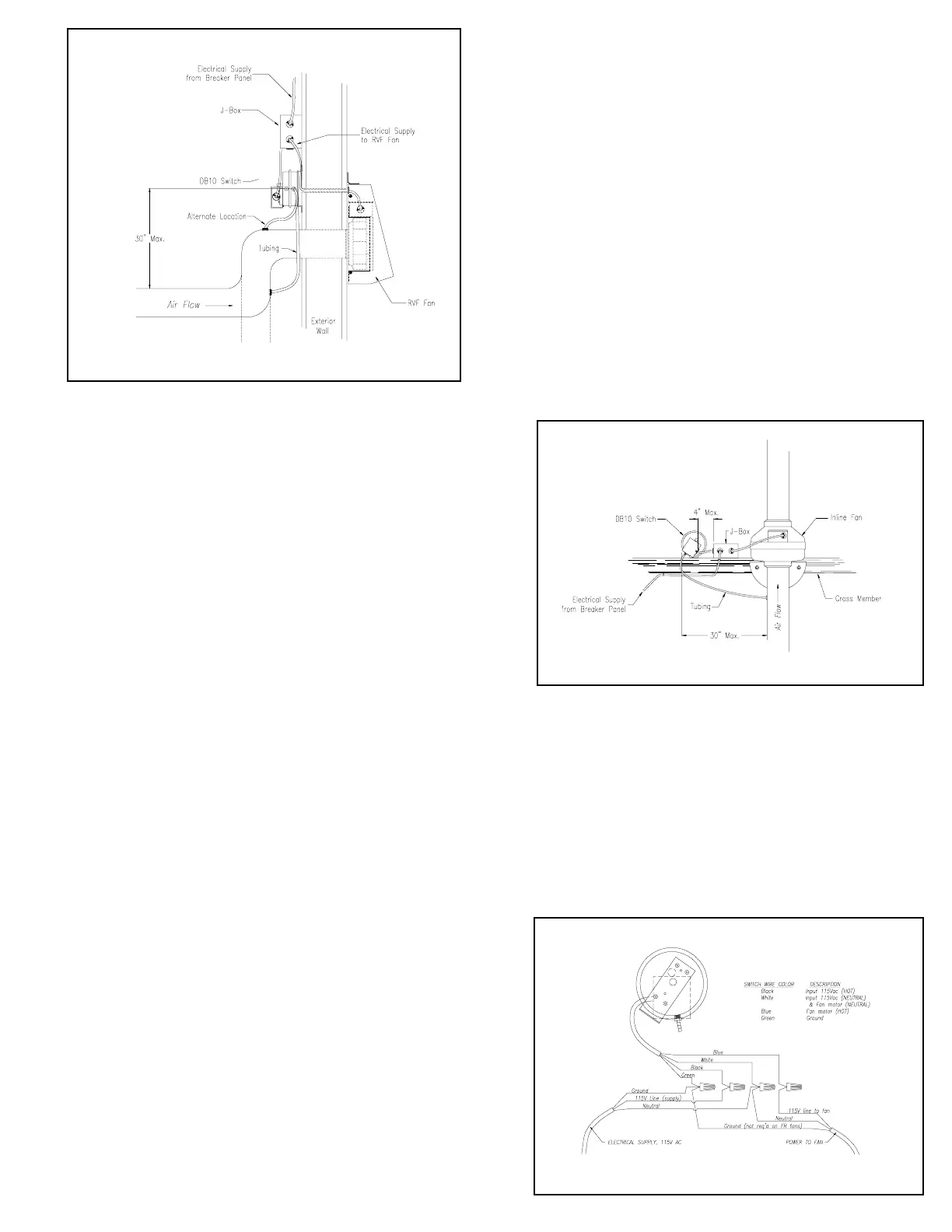
Wiring Procedure
Step 1.
A 4”x4” junction box (J-Box) is recommended for adequate
space for all wiring connections. The box should be mounted a
maximum of 4 inches from the switch. (Refer to illustrations above.)
Step 2.
Using the wire nuts provided, connect the incoming
electrical supply, the switch leads and the power supply to fan as
shown in the schematic on the right.
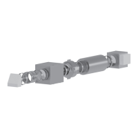
Additional Installation Notes:
DB10 used with an RVF Series Fan
The RVF Series fans create very little resistance against the dryer
fan air flow when the RVF fan is not operating. A minimum
amount of pressure (approximately 0.05” - 0.07”) is required in
order to trigger the switch. For installations where there is a long
horizontal duct run prior to terminating at the fan, it may be
necessary to insert one or two elbows. The elbow(s) increase the
static pressure on the upstream side of the elbow. As illustrated,
the duct pressure tap should then be installed in the upstream side
of the first elbow. The dotted lines show an alternate location for
the pressure tap for systems with one elbow added. As an
alternative to inserting an elbow near the fan, the switch and
pressure tap may be located upstream of an existing elbow (as
shown on Page 2) or may be installed closer to the dryer.
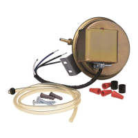
Additional Installation Notes:
DB10 used with an Inline Fan
Unlike the RVF Series, the FR and FX Series fans create enough
resistance to the dryer fan flow to trigger the pressure switch. When
using the switch with an inline fan, the switch and pressure tap
may be installed near the fan or at any point along the duct between
the dryer and the fan. One advantage to locating the switch and
pressure tap near the fan are proximity to one another for servicing,
maintenance, troublshooting, etc.
 Loading...