Positive Pressure Sensor Fan Proving Switch and Fan
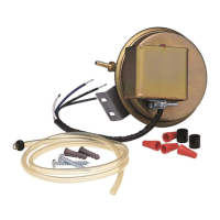
DB10 Kit Includes:
1 DB10 Pressure Switch with Integral Delay
1 3 Section of NPT Tubing
1 Grommet for Tubing
4 Wire Nuts for Electrical Connection
1 Packet with Switch Mounting Hardware
DB10 PRESSURE SENSING SWITCH KIT
INSTALLATION INSTRUCTIONS
IMPORTANT NOTICE: READ and SAVE THESE INSTRUCTIONS for FUTURE REFERENCE.
DB10 Dimensional Data
Pressure Sensor Switch Operation
Fantech’s DB10 is a positive pressure sensing switch which recognizes dryer operation and activates the booster fan from
an independent electrical circuit. This eliminates connections through the dryer circuit which may void the manufacturers’
warranty as well as manual systems which require the attention of the operator or costly current/temperature sensing
systems.
The electrical to the booster fan is connected in series through a normally open terminal on the switch. A pressure tap is
connected to a tip on the side of the switch. When the dryer begins operation, positive pressure in the duct causes the
switch diaphragm to expand closing the circuit to the booster fan. An integral delay-on-make timer in the switch will cycle
the fan on for intervals of 10 minutes. This will continue until the dryer has stopped and the timer delay period has lapsed.
Drying cycles, the booster fan, the delay timer and the pressure switch are not adversely affected by the starting/stopping
intervals.
Installation Guidelines
The DB10 switch can be mounted at any point in the duct between the dryer and booster fan. However, in installations
when the switch is used to control an RVF fan, it may be necessary to locate the DB10 in front of an elbow. (See additional
installation instructions on Pages 2 and 3.) Be certain to allow adequate space for the switch. Refer to the dimensional data
shown below. For optimum switch sensitivity, the diaphragm must be mounted vertically. Refer to the illustrations in the
middle of Page 2 of these instructions for correct and incorrect switch diaphragm positioning. The switch should be
mounted within 30 inches from the point where the pressure tap will be inserted into the dryer exhaust duct.
Installation Instructions
Step 1. Selecting Switch Location
Switch must be located between the dryer
and the booster fan in order to work
properly. Switch can be installed at any
point along the duct run. However, if the
switch is used in conjunction with an RVF
fan, the best location may be upstream of
an elbow. (Refer to Page 3 of these
instructions for additional installation
details.)
DB10599A
1712 Northgate Blvd. - Sarasota, FL. 34234
Phone: (800) 747-1762 Fax: (800) 487-9915
Phone: (941) 351-2947 Fax: (941) 3593828
Web Site www.fantech-us.com