Do you have a question about the Fantech DBF4XL and is the answer not in the manual?
General advice and limitations for installing the DBF4XL fan, including usage restrictions and duct length requirements.
Guidance on how to calculate the total equivalent duct length for proper fan installation, including accounting for bends.
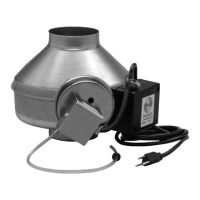
Recommended locations and methods for mounting the booster fan and its associated pressure switch for optimal performance.
Explanation of how the pressure sensor switch detects dryer operation and activates the booster fan automatically.
Guidance on choosing the optimal location for the booster fan based on distance from the dryer and access for maintenance.
Instructions for securely attaching the mounting bracket to a support beam or structure.
Steps for attaching the fan unit to the installed mounting bracket, ensuring proper orientation.
Illustrations showing correct and incorrect diaphragm positioning for the pressure switch in various duct orientations.
Detailed instructions for drilling the duct wall and properly inserting the grommet and tubing for the pressure sensor.
Methods to improve switch sensitivity in high-elevation areas by adjusting tubing and diaphragm placement.
Instructions regarding power supply connection and general safety during installation and operation.
Critical safety warnings to reduce the risk of fire, electric shock, or injury during fan installation and use.
Guidelines for periodic inspection and cleaning of the fan impeller to ensure optimal performance.
Step-by-step guide to diagnose and resolve issues if the fan fails to start when the dryer cycle begins.
Details regarding the product warranty, terms, conditions, and procedures for factory returns.