Do you have a question about the FARFISA INTERCOMS ECHOS EH9262AGCT and is the answer not in the manual?
Technical characteristics of the art.2302 cable, covering conductors, cross-section, material, and impedance.
Guaranteed maximum distances with art.2302 cable for various system configurations.
Installation diagram and description for a single-family video intercom system.
Installation diagram and description for a two-family video intercom system.
Installation diagram and description for a multi-family video intercom system.
Technical specifications of the indoor unit, including power, screen, standard, frequencies, and bandwidth.
Wall-mounting the art.9083 back box at approximately 1.5 meters height.
Removing the terminal block from the video intercom unit for access.
Performing wiring connections according to the electric diagram.
Plugging the terminal block back into the video intercom unit.
Detaching the front side covers to access fixing points.
Securing the video intercom to the back box using supplied screws.
Reattaching the side covers after installation.
Adjusting the screen brightness for optimal viewing angle.
Function of the loudspeaker for communication and receiving calls.
Adjusting communication and ringer volume levels.
Function of the microphone for speaking with the door station.
Indication of communication status or incoming calls.
Button to power on the video intercom and monitor the entrance.
Enabling/disabling audio or entering programming mode.
Indication of temporary audio disable or programming mode.
Button to enable audio communication after a call.
Buttons 1-6 for various services and special functions.
Button to activate the electric door lock.
Indication of door open status or other services.
Description of the 3.5" colour LCD display.
Adjustment of the display colour settings.
Adjustment of the display contrast settings.
Adjusting the microphone audio level.
Adjusting the microphone sensitivity.
Jumpers for matching video signal impedance.
Connecting a button to receive floor calls via specific terminals.
Connecting an actuator module for door open or other function signalling.
Connecting equipment to repeat the call to other points in the home.
Default settings for user address, internal address, and button codes.
Procedure to enter the programming mode using the mute button.
Method to save the video intercom address from the external station.
Procedure for inputting numerical codes and addresses with specific button presses.
Programming user and internal addresses for call reception and system identification.
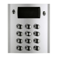
Assigning external door station addresses to specific buttons.
Setting the number of rings for different call types.
Selecting the call melody type for various incoming calls.
Procedure to exit programming mode by repositioning a jumper.
Handling calls originating from the external door station.
Making or receiving calls to/from other users in the system.
Making or receiving intercom calls within the same apartment.
Using buttons for control functions like monitoring external stations.
Default settings for external door station address and initial button assignments.
Steps to enter the programming mode via jumper and button press.
Procedure to exit programming mode by repositioning the J1 jumper.
Explanation of Pn and P1 button functions for entering codes and addresses.
Detailed process for inputting numerical codes and addresses, including pauses and confirmation.
Programming the address for the external door station using codes 231-250.
Programming the address for the first button (Pn) of the VD2121CAG.
Assigning addresses to the first button of additional AG100TS panels.
Setting the duration for which the electric door lock remains activated.
Activating or deactivating system functions based on mode selection.
Assigning call function with camera deactivation to specific buttons.
Restoring camera activation function to previously deactivated buttons.
Changing addresses for up to 20 buttons for custom functions or actuator control.
Resetting special buttons to their automatically assigned addresses.
Restoring all programming settings to factory defaults.
Procedures for receiving and handling calls from the external door station.
Instructions for initiating or responding to calls with other system users.
Procedures for making or receiving intercom calls within the same dwelling.
Using buttons to monitor external stations and manage connections.
Adjusting the screen angle for optimal viewing.
Adjusting display colour and contrast using rear trimmers.
Adjusting microphone and loudspeaker volumes using trimmers.
Eliminating audio feedback (Larsen effect) by adjusting trimmer.
Manually adjusting camera framing horizontally and vertically.
Description of terminal connections and electrical data for modules.
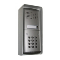
Positioning the outdoor unit camera to avoid direct sunlight or reflections.
Detailed technical specifications for AG20 and AG21 modules.
Pinout and function of terminals for AG20 and AG21 modules.
Essential safety guidelines for installation and product usage, including qualified personnel and electrical safety.
Description of the terminals for the Line Distributor (DV2420).
Explanation of the J1 jumper's function for selecting line termination impedance.
Description of the terminals for the Floor Distributor (DV2421P).
Details on warranty duration, claims process, and validity conditions for the Italian territory.
| Brand | FARFISA INTERCOMS |
|---|---|
| Model | ECHOS EH9262AGCT |
| Category | Intercom System |
| Language | English |