Do you have a question about the FARFISA INTERCOMS 1PXFED and is the answer not in the manual?
Details on changing relay activation time, mode, and bistable operation for relays.
Describes direct relay activation via buttons and the function of door lock release buttons.
Covers emergency procedures and important operational notes for the system.
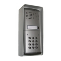
Instructions for installing the push-button panel, including mounting modules.
Guides on adjusting receiver volume, transmitter volume, and anti-feedback settings.
Details on the default programming and codes for the access control keypad.
Procedure for changing the master programming code of the access control keypad.
Instructions for changing individual relay activation codes and deleting them.
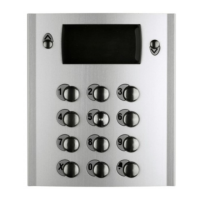
This document describes the FARFISA ONE-WAY AUDIO KIT, an access control keypad (FC52PL) designed for activating two relays with programmable codes.
The FC52PL keypad allows for the activation of two independent relays (RL1 and RL2) using programmable codes. It supports up to 12 codes for each relay, in addition to direct activation. The device can be programmed to operate in various modes, including monostable, bistable, and direct activation via a dedicated key or external push-buttons.
Relay Activation: To activate a relay, the user enters one of the programmed codes followed by pressing key A. If the code is correct, the relay activates, indicated by a green LED, for the programmed time and operating mode.
Bistable Operation: This feature allows relays to be activated for an indefinite time. To activate, the user enters a relay code and presses key A (green LED on). To deactivate, the user enters the same code again and presses key A (green LED off). This function requires proper keypad programming.
Direct Activation: The keypad supports direct activation of relays via key A, provided it has been programmed for this mode. If both relays are programmed for direct activation by key A, both will activate simultaneously.
Door Lock Release Buttons: Two external buttons can be connected to terminals P1, P2, and ground to activate the two relays according to their programmed activation time and mode. P1 activates relay 1, and P2 activates relay 2. If momentarily connected to ground, they will activate for the programmed time.
Programming Features:
Terminals:
LED Indicators:
Acoustic Signals:
Keypad Operation:
Tone Table:
Emergency: In case of power failure, all programmed data is recorded in a nonvolatile memory and will not be lost.
Restoring Default Programming: To delete all programmed codes and restore the keypad to its default settings, switch off the keypad, then switch it on again while holding key B pressed until a confirmation tone is heard.
Important Notes for Installation and Maintenance:
| Brand | FARFISA INTERCOMS |
|---|---|
| Model | 1PXFED |
| Category | Intercom System |
| Language | English |