Do you have a question about the FARFISA INTERCOMS PT520W and is the answer not in the manual?
Two-colour intercom for 4+1 systems with electronic bell.
Beige intercom for 4+1 systems with buzzer and push-button.
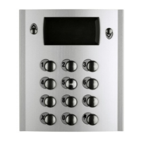
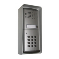
Amplified door stations with built-in intercom and call button.
Transformer for amplified door stations, locks, and name plate lamps.
Power supply for 4+1 systems with call differentiation (buzzer/electronic).
Power supply for 4+1 systems (locks, lamps, speakers, amplifier).
Power supply for systems with private conversation module.
Power supply for intercommunicating systems with automatic switching.
Instructions for basic intercom system operation, door release, and entrance switching.
Operation of intercoms with private conversation module for audio privacy.
Instructions for intercommunicating systems, including connection to door stations.
Guidance on diagnosing and resolving common intercom system faults.
Transformer for door stations, name plate lamps, and electric door lock.
Wiring diagram for 1+1 system with two door stations and automatic switching.
| Brand | FARFISA INTERCOMS |
|---|---|
| Model | PT520W |
| Category | Intercom System |
| Language | English |