4
FARMNAVIGATOR G7 – User Manual
1. Introduction
1.1 Ways of using G7
Thank you for choosing a FARMNAVIGATOR G7!
Now you have the opportunity to:
- Mapyourelds;
- Setupandsaveyourimplements;
- Createguidelinesforyouractivities;
- Savealltheactivitiesdoneintheeld;
- Congure the spray boom and have section control directly on the display during your
treatments;
- Controlsectionsautomatically,whenacompatibledeviceisconnectedtoG7;
- ImportandexportyoujobsandseethemonGoogleEarth™;
- ConnectAuto-SteeringKittotakefulladvantageofdrivingcapabilities;
- Savethepositionofobstaclesontheworkarea;
- ConnectacameraandcontrolitfromG7display;
- UseTerrestrialNavigator(onlyforG7PlusandG7Iso);
- ReceiveRTKcorrectionsviaNTRIPClient(G7Plus,G7IsoandG7Terminal);
- Usegroundcompensationfunction;
- Connect ISOBUS equipment (with Iso Kit).
1.2 Electrical connections
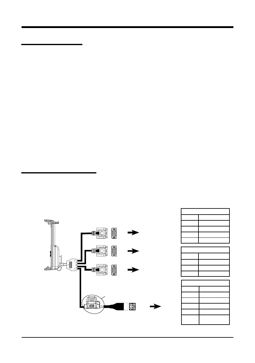
G7 is provided with a bracket and a wiring with connectors to ensure an easy and safe installation
on your tractor.
Wiring harness consists of a 2A protection fuse.
The supply voltage must be within the range 10-35 Vdc.
Follow the instructions included in the package.
Figure 1.2.a - Electrical connections
P5 PIN-OUT
PIN n° Function
2 GPS TX
3 GPS RX
4 GPS VCC
5 GPS GND
P2
P4 PIN-OUT
PIN n° Function
2 DEVICE 2 TX
3 DEVICE 2 RX
5 DEVICE 2 GND
P3 PIN-OUT
PIN n° Function
2 DEVICE 1 TX
3 DEVICE 1 RX
4 DEVICE 1 VCC
5 DEVICE 1 GND
9
EXTERNAL
ALARM
P5
P4
P3
PWR +
PWR -
2A Fuse
6
1
9
5
6
1
9
5
6
1
9
5
GPS
Controller
Generic device
Power
supply


 To Next Page