The FNI MPL-302-105-M is an IP 67 module designed for industrial applications, offering robust input/output capabilities and network connectivity. This manual provides comprehensive information for its installation, operation, and maintenance.
Function Description
The module serves as an IP 67 Input/Output Module, specifically the 302 variant, which indicates an input/output configuration. It supports various communication protocols including EtherNet/IP, ProfiNet, EtherCAT, and CC-Link IEField basic, making it versatile for integration into different industrial control systems. The "105" in the model number signifies a display version with a 2-port switch, enhancing its usability and connectivity options. The "M" indicates a mechanical version with a zinc alloy die-casting housing, ensuring durability in harsh environments.
The module features multiple I/O ports (A-code) and network ports (D-code), as well as power interfaces (L-code). It is designed to handle both digital sensor inputs and output signals. The module includes status indicators for power, network activity, and I/O port status, providing visual feedback on its operational state.
Important Technical Specifications
- Housing: Die-cast aluminum case, pearl nickel plated.
- Housing Class: IP67 (only in plug-in or plug-in style).
- Dimensions (WHD): 65mm222mm25.8mm.
- Installation Type: 2-Through Hole Mounting.
- Ground Bus Accessories: M4.
- Weight: Approximately 670g.
- Operating Temperature: -5°C to 70°C.
- Storage Temperature: -25°C to 70°C.
- Voltage: 18-30V DC.
- Voltage Fluctuation: <1%.
- Input Current at Supply Voltage 24V: <130mA.
- Power Interface (L-code):
- Pin 1: Us+ (+24V)
- Pin 2: Ua-* (0V)
- Pin 3: Us- (0V)
- Pin 4: Ua+* (+24V)
- FE: Functional ground* (FE)
- Total current <9A.
- Network Interface (D-code):
- Port Type: 2 x 10Base-/100Base-Tx.
- Connection: M12, D-Code.
- Cable Types: Shielded twisted pair, min. STP CAT 5/STP CAT 5e.
- Data Transfer Rate: 10/100 M bit/s.
- Maximum Cable Length: 100m.
- Flow Control: Half condition/full condition (IEEE 802.3-PAUSE).
- I/O-Port (A-code):
- Pin 1: +24V, 1A.
- Pin 2: Enter/output.
- Pin 3: 0V.
- Pin 4: Enter/output.
- Pin 5: FE.
- Maximum output current of pins 2 and 4 is 2A. Total current of the module is less than 9A.
Usage Features
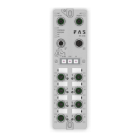
- Module Overview: The module features a clear layout with labeled ports and indicators. Key components include mounting holes, network ports with status indicators, power outlet, DIP switch, I/O ports (0-7), port status indicators, port identification board, power input port, module indicator, and ground connection.
- Electrical Connections:
- Power Interface (L-code): It is recommended to supply sensor/module power and actuator power separately. The total current for all modules should not exceed 9A, even when daisy-chaining the actuator power supply. The FE connection from the housing to the machine must be low impedance and kept as short as possible.
- Network Interface (D-code): Supports 2 x 10Base-/100Base-Tx connections.
- I/O-Port (A-code): For digital sensor input, follow EN61131-2, Type 2 guidelines. Unused I/O port sockets must be covered with end caps to meet IP67 rating.
- Function Indicators:
- PT (Protocol Type): Green for EtherNet/IP, Yellow for ProfiNet, Blue for EtherCAT, White for CC-Link IEField basic.
- US (User Status): Green indicates power is OK. Red indicates voltage >30V or <11V. Flashing red indicates voltage <18V.
- UA (User Application): Green indicates power is OK. Red indicates voltage >30V or <11V. Flashing red indicates voltage <18V.
- SF/MS/RUN (System Fault/Module Status/Run): Closure indicates no error, device initialization. Green light flashing indicates pre-operational state. Green light flashes 1HZ indicates safe operation. Green light flashes 2.5HZ indicates running.
- BF/NS/ERR (Bus Fault/Network Status/Error): Steady green indicates no errors, device EtherCAT communication is working. Closure indicates invalid configuration. Red light flashes 2.5HZ indicates local error. Red light flashes 1HZ indicates application watch timeout. Red light double flash indicates application monitoring timeout.
- I/O Port Status: Indicators for each port show the state (0 or 1), overcurrent, or short circuit conditions.
- Network Port Status (LK1 IN/LK2 OUT): Closure indicates 10Mbit/s bus rate. Flashing green indicates data transmission.
- Module Configuration:
- Restore Factory Settings: Power off, dial 900, power on for 10 seconds, then power off and dial the original code.
- Node Address Configuration: Node address can be assigned by PLC or manually via DIP switches (X100=4, X10=tens, X1=ones). After adjusting the dial code, the device needs to be powered on again.
- Data Mapping: The manual provides detailed tables for process output data and process input data, showing the bit assignments for various functions and port statuses.
- PLC Integration Tutorial: Includes steps for installing the ESI file and configuring the module within OMRON NX1P2 Sysmac Studio Integrated (ECT) for EtherCAT networks. This involves adding the module from the toolbox, configuring the network, and mapping variables.
Maintenance Features
- Safety Information: The manual emphasizes safety precautions, including proper installation by qualified personnel, protection against unauthorized use, and regular checks for damage. It also highlights the importance of using approved cables and avoiding corrosive environments.
- Troubleshooting: The function indicators provide immediate visual cues for diagnosing issues related to power, network communication, and I/O port status (e.g., overcurrent, short circuit).
- Warranty: The manufacturer's warranty coverage and limited liability statement do not cover damage caused by unauthorized tampering, improper use, or owner/operator's obligations.
- EMC Compliance: The device is an EMC Class A product, which may generate RF noise.
- Environmental Considerations: The module is designed to operate within specified temperature ranges and is resistant to corrosive substances, but proper installation and maintenance are crucial to prevent damage.