25
English
Fatal1ty Z270 Professional Gaming i7 Series
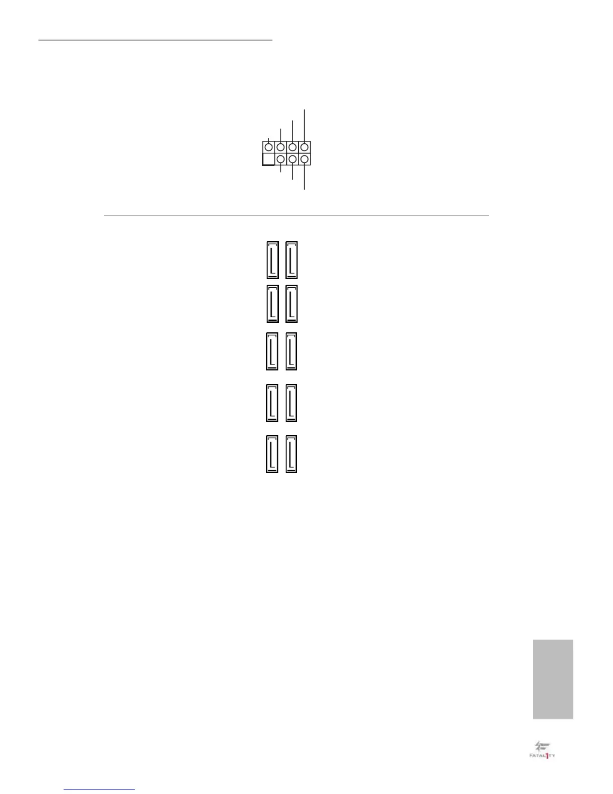
Power LED and Speaker
Header
(7-pin SPK_PLED1)
(see p.1, No. 21)
Please connect the
chassis power LED and
the chassis speaker to this
header.
Serial ATA3 Connectors
(SATA3_0_1:
see p.1, No. 13)
(SATA3_2_3:
see p.1, No. 13)
(SATA3_4_5:
see p.1, No. 14)
(SATA3_A1_A2:
see p.1, No. 15)
(SATA3_A3_A4:
see p.1, No. 16)
ese ten SATA3
connectors support SATA
data cables for internal
storage devices with up to
6.0 Gb/s data transfer rate.
M2_1, SATA3_0 and
SATA3_1 share lanes. If
either one of them is in
use, the others will be
disabled.
M2_2, SATA3_4 and
SATA3_5 share lanes. If
either one of them is in
use, the others will be
disabled.
If M2_3 is occupied by a
SATA-type M.2 device,
SATA3_3 will be disabled.
To minimize the boot
time, use Intel® Z270 SATA
ports (SATA3_0) for your
bootable devices.
1
+5V
DUMMY
PLED+
PLED+