EasyManua.ls Logo

FAURE HERMAN HELIFLU TZN User Manual

FAURE HERMAN HELIFLU TZN
20 pages
To Next Page IconTo Next Page
Page #1 background imageLoading...
Page #1 background image
HELIFLU
TM
TZN
User’s Manual
FAURE HERMAN
Route de Bonnétable
BP 20154 – 72406 La Ferté Bernard
Cedex France
Tel : +33 (0)2 43 60 28 60
Fax : +33 (0)2 43 60 28 70
E-mail : fhprojects@idexcorp.com
FAURE HERMAN METER
4702 N Sam Houston Pkwy West
Suite 100
Houston, TX 77086 (U.S.A)
Tel : +1 713 623 0808
Fax : +1 713 623 2332
E-mail: FHH-Sales@idexcorp.com
FAURE HERMAN
Office #738, Building #6EB
Dubai Airport Freezone (DAFZA)
Dubai (U.A.E)
Tel : +971 4260 0381
Fax : +971 4260 0319
Email : fhsalesme@idexcorp.com
www.faureherman.com
Question and Answer IconNeed help?

Do you have a question about the FAURE HERMAN HELIFLU TZN and is the answer not in the manual?

FAURE HERMAN HELIFLU TZN Specifications

General IconGeneral
BrandFAURE HERMAN
ModelHELIFLU TZN
CategoryMeasuring Instruments
LanguageEnglish

Summary

Chapter 1: Introduction to TZN Meters

Signal Generation Principle

Explains how the TZN flow meter generates an electrical signal.

Chapter 2: Meter Components by Meter Size

Meter Body Description

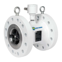
Details the construction and materials of the meter body.

Measurement Cartridge Types

Describes different types of measurement cartridges available.

Chapter 3: Equipment Receipt, Storage and Handling

Receipt and Storage Procedures

Guidelines for receiving, inspecting, and storing the flowmeter.

Risk Analysis and Safety Requirements

Analysis of risks and essential safety requirements according to standards.

Chapter 4: Installation and Operation

Installation and Handling Guidelines

General recommendations for installing and handling the flowmeter.

Pipe Preparation and Alignment

Procedures for preparing and aligning piping for meter installation.

Meter Installation Best Practices

Specific best practices for installing the TZN meter.

Gasket Selection and Torque

Guidance on selecting gaskets and applying correct torque.

ATEX Electrical Component Criteria

Criteria for ATEX certified electrical components.

ATEX Intrinsically Safe and Flameproof Data

Data tables for ATEX intrinsically safe and flameproof certifications.

Recommended Strainer Size by Meter

Table recommending strainer mesh sizes based on meter size.

ATEX & IEC Ex Installation Guidelines

Specific guidelines for ATEX and IEC Ex installations.

General Safety Information

Overall safety precautions for operating the equipment.

Electrical Installation Procedures

Step-by-step procedures for electrical installation.

Wiring Diagrams

Diagrams illustrating typical electrical connections.

Safety Considerations and Procedures

Comprehensive safety considerations and operational procedures.

Chapter 5: Commissioning

Initial Pipe Filling and Purging

Procedures for filling the pipe and purging air during commissioning.

Avoiding Gas Pockets and Over-operation

Advice on preventing gas pockets and avoiding over-operation.

Chapter 6: Maintenance

Routine Maintenance Recommendations

General recommendations for routine maintenance.

Chapter 7: Troubleshooting

Common Problems and Solutions

Table of common flowmeter problems and their possible solutions.

Appendix 2 - K-factor - Flowrate/Frequency

Chapter 8: Replacement - Repair

Preamplifier Replacement

Step-by-step guide for replacing the preamplifier.

Coil Replacement - Metal Retaining Ring

Coil Replacement - Engineered Polymer Ring

Measurement Cartridge Replacement (≤ 3" Size)

Measurement Cartridge Replacement (4"-14" Size)

Measurement Cartridge Replacement (> 16" Size)

Chapter 9: Equipment Removal

Depressurization and Draining Before Removal

Procedures for safely depressurizing and draining equipment before removal.

Appendix 1 - Alternative Configurations

Appendix 2 - Meter Drawings by Size and Type

Nominal Size STD ≤ 3"

Diagram illustrating the STD meter configuration for sizes up to 3 inches.

Nominal Size CUS ≤ 3"

Diagram illustrating the CUS meter configuration for sizes up to 3 inches.

Nominal Size STD 4"-14"

Diagram illustrating the STD meter configuration for sizes 4 to 14 inches.

Related product manuals