CONNESSIONI/CONNECTIONSBRANCHEMENTS/ANSCHLÜSSE SPECIFICHETECNICHE/TECHNICALSPECIFICATIONS
CARACTÉRISTIQUESTECHNIQUES/TECHNISCHEDATEN
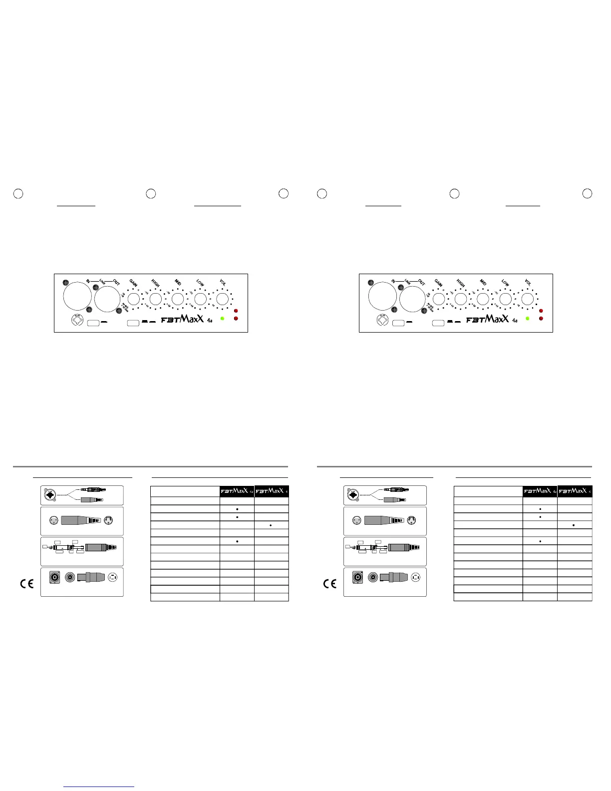
CONTROLLICONTRÔLES CONTROLSSTEUERUNGEN
12 21
33
LatosaldatureLatocontatti
1.Massa2.Fase+3.Fase-Schermo(Shield)Caldo(Hot)Freddo(Cold)
XLR
12 21
33
Côtésoudures
Geschlosseneseite
Côtécontacts
Kontaktseite
1.Massa2.Fase+3.Fase-(Shield)(Hot)(Cold)
XLR
*SPEAKONèunmarchioregistratoNEUTRIK*SPEAKONestunemarquedéposéeNEUTRIK *SPEAKONisaregistredtrademarkofNEUTRIK*SPEAKONisteineingetragenesWarenzeichenvonNEUTRIK
1+ PositivePositivo/1+ Positive
1- NegativeNegativo/1- Negative
Speakon*Speakon*
PresaSpeakonPriseSpeakon
SpeakonStecker
1+1+
2+2+
2-2- 1-1-
XLR-F(micro)
1=SHIELD
2=HOT
3=COLD
LINE
JACK
12
3
NEUTRIKXLR/JACK-COMBO
XLR-F(mic)
1=SHIELD
2=HOT
3=COLD
LINE
JACK
12
3
NEUTRIKXLR/JACK-COMBO
Jackstereo/bilanciato/balancedStereojackbalancée
Stereobuchse
TIP=Positive(+orhot)TIP=Positive(+orhot)
SLEEVE=ShieldorgroundSLEEVE=Shieldorground
RING=Negative(-orcold)RING=Negative(-orcold)
TIPTIP
TIPTIP
RINGRING
RINGRING
SLEEVESLEEVE SLEEVESLEEVE
F ID UK
Configuration
Konfiguration
22
300+100
4/8
300
50Hz-20kHz50Hz-20kHz
600
9898
123/126123
1x320
25.4+trichter 25.4+trichter
25.4+pavillon 25.4+pavillon
1x320
407x634x330407x634x330
12
16
2xspeakonXLR-Jack
Impédancenominale
Nominalimpedanz
Amplificateurrecommandé
Empfohleneverstarkerleitung
Amplificateurinterne
IntegriertenVerstärker
Wrms
Wrms
@-5dB
(IEC268-5)Wrms
@1W/1mdB
dB
mm
mm
(LxAxP)mm
(BxHxT)mm
kg.
voies/weg
ohm
Réponseenfréquence
Frequenzgang
Courtterme
Spitzenbelastbarkeit
Sensibilité
Empfindlichkeit
MaximumSPL
Maximalershalldruck
Unitéhautefrequence
Wooferbassesfréquence
Hohefrequenzeinheit
Bass-Woofer
Dimensions
Abmessungen
Poids
Gewicht
Connecteurs
Eingange
Configurazione
Type
22
300+100
4/8
300
50Hz-20kHz50Hz-20kHz
600
9898
123/126123
1x3201x320
25.4+tromba 25.4+tromba
25.4+horn 25.4+horn
407x634x330407x634x330
12
16
2xspeakonXLR-Jack
Impedenzanominale
Nominalimpedance
Amplificatoreraccomandato
Recommendedamp.
Amplificatoreinterno
Built-inamplifier
Wrms
Wrms
@-5dB
(IEC268-5)Wrms
@1W/1mdB
dB
mm
mm
(LxAxP)mm
(WxHxD)mm
kg.
vie/way
ohm
Rispostainfrequenza
Frequencyresponse
Shortterm
Shortterm
Sensibilità
Sensitivity
MassimoSPL
MaximumSPL
Unitàbassefrequenze
Unitàaltefrequenze
Lowfrequencywoofer
Highfrequencydriver
Dimensioni
Dimensions
Peso
Weight
Connettoridiingresso
Inputconnectors
#IN-link-OUT
#GAIN
#HIGH/MID/LOW
#VOL
#GNDLIFT
.
A.D.A.P
PWR:
:Presediingressoeduscitabilanciateelettronicamente.
Lapresa“IN”XRL+Jack-Combo-consenteilcollegamentodiun
microfonodinamicoabassaimpedenzaounsegnalepreamplificatocome
quelloinuscitadaunmixer;l’uscita“OUT”XLRèconnessainparallelo
(link)conl’ingresso“IN”permettendoilcollegamentodipiùdiffusoriconlo
stessosegnale.
:Regolalapreamplificazionedelsegnaleproveniente
dall’ingresso“IN”ottimizzandolaalcorrettofunzionamentodelcircuitodi
canale.PerunaequilibrataregolazionedelGain,posizionarelamanopola
delVolumeacirca
3/4dellasuacorsain
sensoorario,e
regolareilGain.
:
Controlliditonoche
permettonodi
modificarelatimbrica
delsuono.Icontrolli
ditonosonoposti
elettronicamente
dopoilcontrollodel
Gainelaloro
esaltazionepuò
provocarelasaturazionedelcanale:inquestocasooccorreagiresul
controllodelGain.Conlamanopolainposizionecentrale(0)nonavviene
alcunaalterazionetimbrica.
:Potenziometrodivolumecheregolaillivellogeneraledelsegnale.
Normalmentelemiglioriprestazionisiottengonoconlamanopola
posizionataacirca3/4dellasuacorsaeconilGainregolato inmododa
ottenereillivellodesiderato.
:Interruttoreperlaseparazioneelettricatrailcircuitodi
massaeilcircuitoditerra.Conilpulsantepremuto(on)lamassadei
segnaliiningressovieneelettricamentescollegatadalcircuitoditerra
(identificatonellochassis);nelcasosimanifestiunronziosuldiffusore
questaposizioneprovvedeadapriregli“anellidimassa”,spessocausadi
talidisturbi.Conilpulsanterilasciatolamassadeisegnaliiningresso
vieneelettricamentecollegataalcircuitoditerradell’apparecchio
(identificatonellochassis).
:Processoreperlaprotezionedeitrasduttoridalleeccessive
tensioni;quandoilsegnaleaudioraggiungelasogliadipericoloperi
componentiilsistemaintervieneautomaticamenteattenuandolatensione
delsegnaleriportandoloaldisottodeilimiti:itempidireazionedelsistema
sonorapidissimi.NeldiffusoreFBTMaxXsonopresentiduecircuitidi
controlloseparati,perlealteebassefrequenze;laloroentratainfunzione
vienesegnalatadall’accensionedeileds“HF”e“LF”.
Ledchesegnalal’accensionedelsistema.
UTILIZZAREILGROUNDLIFTSOLOPER
SEGNALIBILANCIATI
#LINE/MIC:Posizionarel’interruttorein“MIC”sesicollegaunmicrofono
oundispositivoabassaimpedenza;in“LINE”perilcollegamentodi
sorgentidisegnaleadaltolivello.
#IN-link-OUT
#GAIN
#HIGH/MID/LOW
#VOL
#GNDLIFT
A.D.A.P
PWR:
:Prisesd’entréèetdesortie,équilibrées
électroniquement.Laprise“IN”(XLR+Jack-Combo)permetderelierun
microdynamiquebasseimpédanceouunsignalpréamplifié,commecelui
venantd’unmixeur;lasortie“OUT”(XLR)estreliéeenparallèle(link)à
l’entrée“IN”pourpermettrelaconnexiondeplusieursenceintesavecle
mêmesignal.
:Règlelapréamplificationdusignalvenantvenantdel’entrée“IN”
toutenl’optimisantpourlefonctionnementcorrectducircuitducanal.
PourréglerdefaçonéquilibréeleGain,tournerleboutonduVolumedans
lesensdesaiguilles
d’unemontre,pour
lepositionneraux
3/4environdesa
course,puisréglerle
Gain.
:
Contrôlesdes
tonalitéspermettant
demodifierletimbre
duson.Les
contrôlesdela
tonalitésesituent,
auplan
électronique,aprèslecontrôleduGainetunniveautropélevépeut
provoquerlasaturationducanal:danscecas,ilfaudraagirsurlecontrôle
duGain.Aucunealtérationdutimbreneseproduitsileboutonsetrouve
enpositioncentrale(0).
:Potentiomètreduvolumeréglantleniveaugénéraldusignal.
Normalement,onobtientlesmeilleuresperformanceslorsquelebouton
estpositionnéaux3/4environdesacourseetleGainestréglédefaçonà
obtenirleniveaudésiré
:Interrupteurpourlaséparationélectriquedescircuitsde
masseetdeterre.Sionappuiesurlebouton(on)lamassedessignaux
d’entréeestdéconnectéeélectriquementducircuitdeterre(indiquédans
lechâssis);danslecasdebourdonnementdel’enceinte,cetteposition
ouvreles“anneauxdemasse”,quisontsouventlacausedecesparasites.
Lorsqueleboutonestrelâché,lamassedessignauxd’entréeestreliée
électriquementaucircuitdeterredel’appareil(indiquédansle
châssis).UTILISERLEGROUNDLIFTUNIQUEMENTPOURLES
SIGNAUXÉQUILIBRÉS.
:Processeurservantàlaprotectiondestransducteurscontreles
tensionsexcessives;lorsquelesignalaudioatteintleseuildedangerpour
lescomposantsdusystème,ilsedéclencheautomatiquementetréduitla
tensiondusignalpourleramenerendessousdeslimites:lestempsde
réactiondusystèmesonttrèsrapides.L’enceinteFBTMaxXestéquipée
dedeuxcircuitsdecontrôleséparés,pourleshautesetbasses
fréquences;lesled“HF”et“LF”s’allumentlorsqu’ilsentrentenfonction.
Laledsignalequelesystèmeestsoustension.
#LINE/MIC:Positionnerlecommutateursur“MIC”sionrelieunmicroou
undispositifbasseimpédance;sur“LINE”sionreliedessourcesdesignal
dehautniveau.
#INlinkOUT:
#LINE/MIC:
#GAIN:
#HIGH/MID/LOW:
#VOL:
#GNDLIFT:
#A.D.A.P.:
#PWR:
Inputandoutputsockets,electronicallybalanced.The
“IN”XLR+Jackcombosocketallowsconnectionofadynamicmicrophone
atlowimpedanceorofapre-amplifiedsignalsuchasamixerlineout;the
“OUT”socketisconnectedinparallel(link)withtheinput“IN”allowing
multipleconnectionofmoresystemswiththesamesignal.
switchtoselecteither“MIC”positionifamicrophoneoralow
frequencyapplianceisconnected;the“LINE”positionallowsconnection
ofhighlevelsignalsources.
regulatespre-amplificationofthesignalcomingfromtheinput
“IN”,ensuringperfectoperationofthechannelcircuits.Forawell-
balancedgainadjustment,settheVolumetoapprox¾clockwise,then
adjustthegainaccordingly.
3-bandequalisation
tomodifythesound
tone.These
controlsare
electronicallypost-
gainandifboosted
canclipthe
channel:inthiscase
adjustthegain
control
anticlockwise.
Whenthe
potentiometersare
setto“0”thetone
remainsunchanged.
volumepotentiometertocontrolthechannelsignallevel.Normally
optimalchannelcircuitperformanceisachievedwiththeknobpositioned
atapprox.¾clockwiseandthegaincontrolsettothedesiredlevel.
2-positionselectorforseparatingthesignalsourceground
andtheamplifiergroundcircuits.ON:thesignalgroundiselectrically
disconnectedfromtheamplifiergroundcircuit(thechassis).Ifhumis
heardintheloudspeakers,theONpositionbreaksthegroundloop,often
thecauseofthisinterference.OFF:thegroundoftheinputsignalsis
electricallyconnectedtotheamplifiergroundcircuit(thechassis).USE
GROUNDLIFTONLYWITHBALANCEDSIGNALS.
processorcircuitwhichprotectsthetransducersfrom
excessivetensions;whentheaudiosignalreachesthedangerous
thresholdforthetransducers,theA.D.A.P.systemautomatically
intervenesbyreducingtheamountofsignalwithinacceptablelimits:the
timereactionofthesystemsareveryfast.FBTMaxXspeakersystem
featurestwoseparateprotectionsystems,bothforthelowfrequencyand
thehighfrequencydrivers;theactivationoftheseprotectionsis
recognisablethroughthe“HF”and“LF”ledslightingupinthecontrol
panel.
ledsignaltoindicatetheswitchingonofthesystem.
#IN-link-OUT
#LINE/MIC
#GAIN
#HIGH/MID/LOW
#VOL
#GNDLIFT
ADAP
PWR
:ElektronischbalancierteEin-undAusgangsbuchsen.
Die"IN"XRL+Jack-Combo-BuchsegestattetdenAnschlusseines
dynamischenMikrophonsniedrigerImpedanzbzw.einesvorverstärkten
Signals,wiezumBeispieldesAusgangssignalseinesMischpults;durch
denparallel(link)mitdem"IN"Einganggeschalteten"OUT"XLRAusgang
lassensichmehrereLautsprecherandasgleicheSignalanschließen.
:StellenSiedenSchalterauf"MIC",wennSieeinMikrophon
bzw.eineVorrichtungniedrigerImpedanzanschließen;auf"LINE"fürden
AnschlussvonSignalquellenhohenPegels.
:SteuertdieVorverstärkungdesvom"IN"Eingangkommenden
SignalsundstimmtsieoptimalaufdieFunktiondesKanalkreisesab.Zur
ausgeglichenenGain-EinstellungsolltenSiedenLautstärkeregleraufca.
3/4Positionim
Uhrzeigersinn
drehenund
anschließenddie
Vorverstärkung
regeln.
:
Tonsteuerungenzur
Einstellungdes
Klangbilds.Die
Tonsteuerungen
sindderGain-
Einstellung
elektronisch
nachgeschaltet,sodasseinÜbersteuernzurSättigungdesKanalsführen
kann:VerwendenSieindiesemFalldieGain-Steuerung.BeiDrehgriffin
mittlererPosition(0)wirddasKlangbildnichtbeeinflusst.
:PotentiometerzurRegelungdesallgemeinenLautstärke-
Signalpegels.NormalerweiseerhaltenSiediebesteWiedergabebei
Lautstärkeregleraufca.3/4Positionundmiteineraufdiegewünschte
LautstärkeabgestimmtenGain-Einstellung.
:SchalterzurelektrischenTrennungvonMasse-und
Erdkreis.BeigedrückterTaste(on)wirddieMassederEingangssignale
elektrischvondem(imChassisgekennzeichneten)Erdkreisgetrennt;
solltederLautsprecherbrummen,öffnensichinderPosition"on"die
"Massekreise"alshäufigsteUrsachedieserStörung.Beiausgerasteter
TastewirddieMassederEingangssignaleelektrischmitdem(imChassis
gekennzeichneten)Erdkreisverbunden.VERWENDENSIEGROUND
LIFTNURIMFALLBALANCIERTERSIGNALE.
:SchutzprozessorderTransmittervorÜberspannungen;wenndas
AudiosignaldieGefahrenschwellefürdieKomponentenerreicht,greift
dasSystemautomatischdurchAbschwächenderSignalspannungunter
dieGrenzwerteein:DieAnsprechzeitdesSystemsistäußerstkurz.Im
LautsprecherFBTMaxXsindzweiseparateSteuerkreiseintegriert,u.z.
fürdiehohenundniedrigenFrequenzen;dieEinschaltungwirddurch
AufleuchtenderLed"HF"und"LF"gemeldet.
:LedzurAnzeigederSystemeinschaltung.
XLR
1-Gnd
2-Hot
3-Cold
GNDLIFT
LF
PWR ADAP
.
MICLINE
HF
JACK
1
3
2
300+100W-PROCESSEDACTIVEMONITOR
25
XLR
1-Gnd
2-Hot
3-Cold
GNDLIFT
LF
PWR ADAP
.
MICLINE
HF
JACK
1
3
2
300+100W-PROCESSEDACTIVEMONITOR
 Loading...