VAIE 2000 | Voice Alarm Integrated Systems System Manual | 2013
UK
62
VAC 2006 • VAR 2006
See details on page 76.
2. GENERAL DESCRIPTION
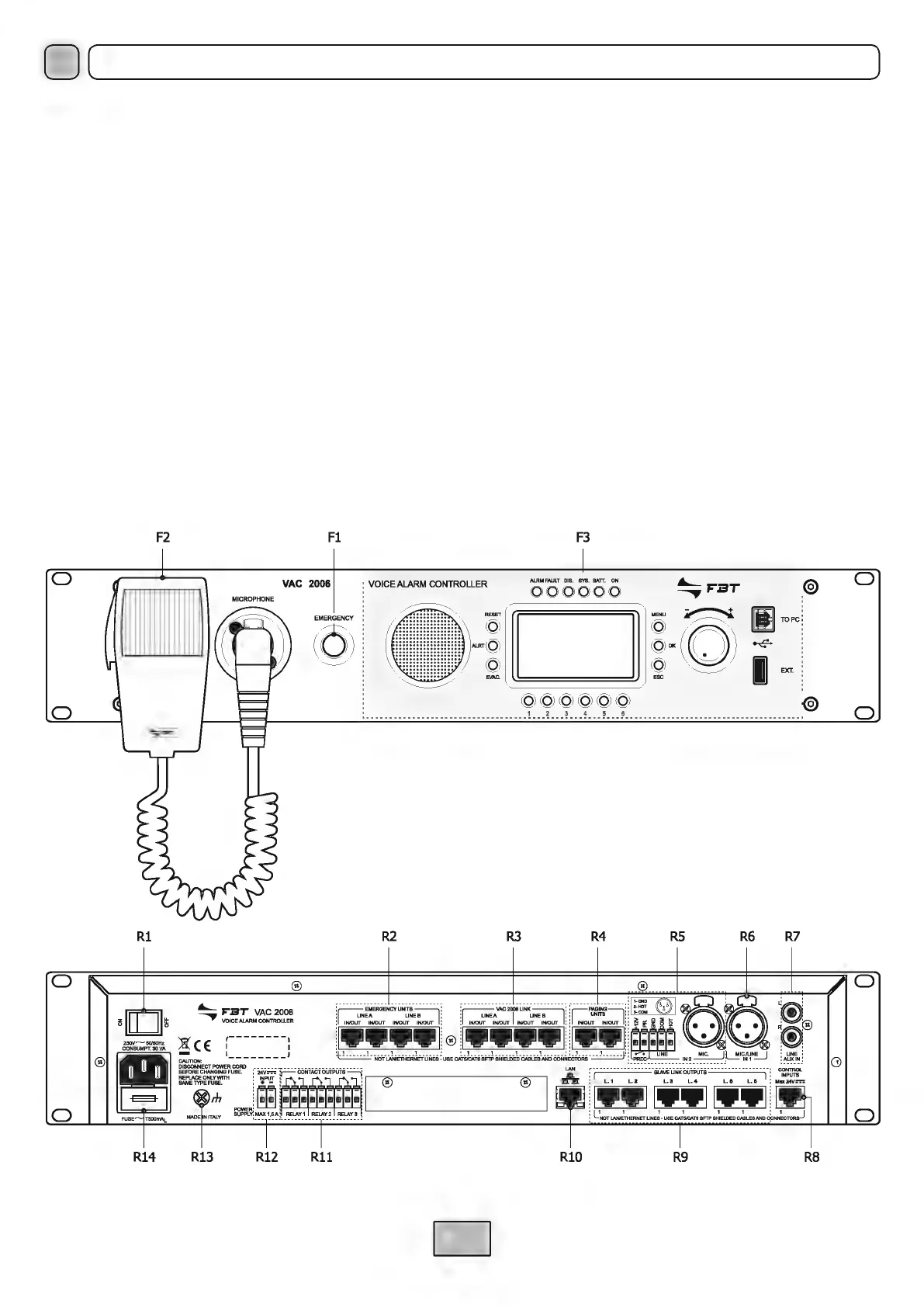
2.1 VAC 2006 CONTROLLER
F1. Flush-mounted push-button for activating the Manual Emergency mode (EMERGENCY).
F2. Hand-held microphone with a Push-to-Talk (PTT) key for live emergency announcements.
F3. Backlit black-and-white graphic display, 128 x 64 pixels.
R1. ON/OFF switch.
R2. Inputs for connecting remote emergency microphone stations (FMD 2012, FMD 2001
).
R3
. Sockets for connections between VAC 2006 controllers (up to 6 units).
R4.
Input for connecting broadcast paging units (MBT 1106, MBT 1112).
R5
. Balanced input for a microphone or outside source / Terminal block for connecting a precedence contact.
R6. Input for external microphone.
R7. Input for connecting an external source of music.
R8. 7 monitored digital inputs for control via external peripheral units.
R9. 6 output lines for connection to amplifiers of the DPU range and/or VAIE 2250 compact systems and/or VAR 2006 routers.
R10. Socket for connecting a Local Area Network with TCP/IP protocol for an Ethernet 10/100 network.
R11. 3 relay outputs for signalling towards external peripheral units.
R12. Terminals for 24 VDC external power supply.
R13. Frame earthing connection.
R14. Plug for 230 VAC mains power supply, with built-in fuse.
o
F2
Fl
o
VAC
2006
li
MICROPHONE
EMERGENCY
©
o
Rl
o
o
R14
R13 R12
Rll
F3
:
VOICE
ALARM
CONTROLLER
000000
•
=
□
@
-@
.
.
~
....__
F":ST
........,,
@@@@@@
~
■
- - - - - - - - - - - - - - - - - - - - - - - - - - - - - - - - - ! . --~ ---~ --.1. --~---~----
■
- - - - - - - - - - - - - - - - - - - - - - - - -
■
- - - - - - - 1
R2
R3
R4
R5
R6 R7
RlO
R9
R8
D
o
o
o
o
 Loading...