6
16. Once the leak rate is established, do not adjust the
leak valve. Open the pressure valve all the way
and allow the line pressure to drop to zero. Leave
the pressure valve open all the way. Continue to
drain until there is no more product draining. Turn
the submersible pump on at the dispenser and
direct the uid into a suitable receptacle while
observing the pressure gauge, which should not
increase above 18 PSI. Turn the submersible
pump off and wait at least one minute. Turn the
submersible pump back on at the dispenser and
observe that the pressure does not increase above
18 PSI. This step veries the leak detector has
detected a leak equivalent to approximately 3 GPH
@ 10 PSI as required by the EPA.
17. Close the leak valve and observe the pressure
increase to full pump pressure. Turn the
submersible pump off and drain the pressure back
to zero.
18. Turn the pump off at the load center, and remove
the test xture, and replace the pipe plug after
applying UL-classied, non-hardening, non-toxic
pipe thread sealant.
STP-MLD+ Line Leak Indicator Testing
19. As a nal check to assure the leak detector has
been installed and is working properly, before
leaving the station perform the following check
(two people are required to perform this check).
a. Turn the submersible pump on at the
dispenser. Dispense product into a ve-gallon
container to assure full ow is being obtained.
b. Leaving the dispenser switch turned on, turn
the power off at the submersible pump
circuit breaker (load center) and open the
nozzle to release pressure. Let stand idle for
approximately 15-30 seconds.
c. With the nozzle open, turn on the power at
the submersible pump circuit breaker (load
center). The ow out of the still open nozzle
should be no more than 3 GPM.
d. Close the nozzle with the submersible pump
still running and wait for 15 seconds or until
you feel the pressure increase in the line when
the leak detector opens. Open the nozzle and
full ow should be obtained.
Note: The submersible pumps and the dispensers must
be wired to different circuit breakers for the above
test to work. Also, some dispensers may not allow
for this test since low pressure may put it into error
(i.e. blender dispensers).
Note: Instructions 12 through 19 can also be used to
check a leak detector after it has been in service for
a period of time to assure it is functioning properly.
Mechanical line leak detectors are devices that are
subject to wear with usage. However, FE Petro
®
always recommends that the leak detector is in
compliance with US EPA requirements.
If the above results cannot be obtained, review the
installation instructions to assure the leak detector was
installed properly. If everything has been done correctly
and the results still cannot be obtained, contact the factory.
20. Fill out the warranty registration form completely
and return to the factory immediately after
completing the installation of the leak detectors.
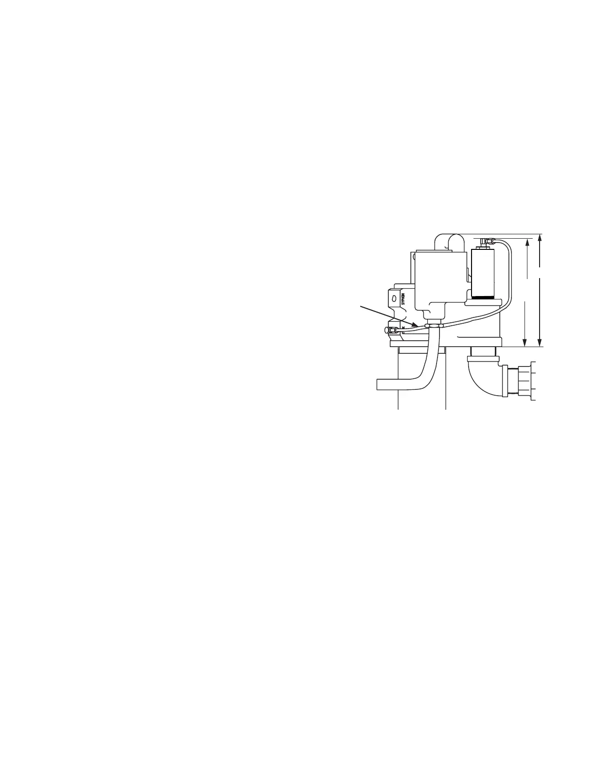
10.65
10.32
(Ref)
Figure 2
STP-MLD+ Vent
Tube connected to
tank port
 Loading...