Do you have a question about the Feasa Low Light LED Analyser and is the answer not in the manual?
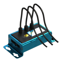
The Feasa LED Analyser Low Light Functional Version is an instrument designed for testing the color and intensity of Light Emitting Diodes (LEDs) in various test processes, particularly in low-light situations such as backlit switches and panels. It supports up to 10 flexible Fiber-Optic Light Guides, which are individually mounted over the LEDs under test to capture emitted light. The raw data from the LEDs is stored internally and can be read out via Serial or USB interfaces.
The core function of the Feasa LED Analyser is to capture and store parameters of LEDs, including color, intensity, xy chromaticity, u'v' chromaticity, dominant wavelength, and correlated color temperature (CCT). This data is then available for retrieval and analysis. The device offers both automatic and manual capture modes.
In Auto Capture mode, the analyser automatically determines the correct settings to capture LED data based on intensity. For a 10-channel unit, data for all 10 LEDs are captured simultaneously. This mode uses a wide intensity range suitable for both dim and bright LEDs.
Manual Capture mode allows users to select from five pre-selected exposure time ranges (Low, Medium, High, Super, Ultra) for capturing LED data. Higher ranges lead to faster test times due to shorter exposure. This mode is recommended for testing LEDs of similar intensity to achieve better results.
The analyser processes the raw data to derive various color and intensity metrics. Colors are represented on a 360° circular color wheel using a single value called Hue, expressed in degrees (e.g., Red near 0°, Green near 120°, Blue near 240°). Saturation, a relative output, describes the degree of whiteness, with 0% representing pure white and 95-100% representing pure color. Intensity is measured on a linear scale from 0 to 99,999, with all measurements being relative to a fixed standard calibration.
User Calibration Mode allows for storing up to 10 different calibration sets. Users can adjust parameters such as relative intensity, absolute intensity, xy offset, wavelength offset, and RGB gains for each set. This is particularly useful for testing boards with different LED color options. Feasa provides a UserCal program for this process, though manual calibration is also possible.
The device supports Daisy Chain Mode, enabling communication with multiple LED Analyser units to simplify wiring and save connections. This can be implemented via USB or Serial RS232. In a daisy chain, the first analyser connects to the computer, and subsequent analysers are interconnected. Each analyser in the chain (except the first in USB mode) requires external 5V power. Commands can be sent to activate specific analysers or to initiate a global capture across all analysers in the chain.
Set commands store settings permanently in the on-board Flash memory (limited to ~100,000 writes to prevent corruption in high-volume production).Put commands write settings to RAM, which are not retained after power-off. Put commands are recommended for high-volume testing to prolong analyser life.Get commands are used to read captured data.
getRGBI##: Retrieves Red, Green, Blue, and Intensity values for a specific fiber.getHSI##: Retrieves Hue, Saturation, and Intensity values for a specific fiber.getxy##: Retrieves xy Chromaticity values (for White LEDs).getuv##: Retrieves u'v' Chromaticity values (for White LEDs).getwavelength##: Retrieves dominant wavelength.getWI##: Retrieves dominant wavelength and intensity.getcct##: Retrieves correlated color temperature (CCT).getintensity##: Retrieves intensity value.getABSINT@@: Retrieves absolute intensity value (requires calibration with a Feasa LED Spectrometer).getfactor: Retrieves the exposure factor.getaverage: Retrieves the number of captures to average.getBAUD: Retrieves the current baud rate.getHW: Retrieves hardware version.getSTATUS: Retrieves a summary of analyser details.getSERIAL: Retrieves the analyser's serial number.getVERSION: Retrieves firmware version.getINTGAIN##: Retrieves intensity gain factor.getXOFFSET##, getYOFFSET##: Retrieves x and y chromaticity offsets.getWAVELENGTHOFFSET@@: Retrieves wavelength offset.getABSINTMULT@@: Retrieves absolute intensity correction factor.getcalibrationdate: Retrieves the user calibration date.BusFree: Deactivates all active analysers on the daisy chain bus.BusGet####: Activates a specific LED Analyser by its serial number.BusC: Initiates an automatic range capture for all analysers in the daisy chain.BusC#: Initiates a manual range capture for all analysers in the daisy chain.BusCE####: Polls a specific LED Analyser to verify capture completion.getVERSION command allows checking the firmware version.User Calibration Mode allows users to fine-tune and save calibration settings. Feasa recommends selecting a capture range that yields Relative Intensity Readings between 55K and 85K for optimal stability.set/putFACTOR## commands allow adjusting the exposure factor (01 to 15) for all fibers, useful for testing very dim LEDs.set/putINTGAIN## commands allow adjusting the intensity gain factor (050-200, default 100) for each fiber to balance intensity readings across similar LEDs.set/putXOFFSET##0.xxx, set/putYOFFSET##0.xxx, and set/putWAVELENGTHOFFSET@@±## commands allow setting offsets for chromaticity and wavelength values, useful for matching manufacturer specifications.setBAUD command allows changing the baud rate for serial and USB ports, which can improve test times.enableeot and disableeot commands control the use of an EOT character (ASCII 04) in addition to CR+LF, which can be useful for multi-line commands.| Brand | Feasa |
|---|---|
| Model | Low Light LED Analyser |
| Category | Measuring Instruments |
| Language | English |