IOM-F -860_860U
INSTALLATION, OPERATION, MAINTENANCE
Maintenance Manual
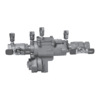
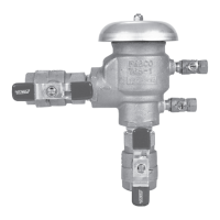
Series 860 Reduced Pressure Zone Assemblies
Models 860, LF860, 860U & LF860U
1
/2"- 2" (15 – 50mm)
Read and understand this manual prior to installing,
operating or servicing this equipment.
Series 860
Table of Contents
Feature and Operating Procedures................................ 2
Vandalism.................................................... 2
General Service Procedures ..................................... 3
Cut-A-Way Drawing ............................................ 3
Troubleshooting Guide ......................................... 4
Check Module Disassembly ..................................... 6
Check Module Seal Replacement................................. 6
Check Module Re-Assembly..................................... 7
Relief Valve Repair............................................. 7
Testing ...................................................... 9
Air Gap Drain Installation Instructions.............................. 9
Exploded View ...............................................10
Parts List ................................................... 10
Repair Kits .................................................. 11
Freeze Protection............................................. 11
Main Valve Draining Procedure (
1
/2" - 2")........................... 11
Warranty.................................................... 12
WARNING
!
Read this Manual BEFORE using this equipment.
Failure to read and follow all safety and use information
can result in death, serious personal injury, property
damage, or damage to the equipment.
Keep this Manual for future reference.
NOTICE
If the unit is installed where a protective device is recommended may be
a problem, the assembly should be protected and secured. On
1
/2" through
2" (15 – 50mm) units the handles of shutoff valves can be removed to
discourage tampering. A protective enclosure can be installed over the unit
to discourage vandals. If an enclosure is used, it should be installed so that
adequate clearance is available for maintenance and testing. Consult local
codes before installing any type of protective enclosure.