Ethernet-I/P Fieldbus Expansion Unit
PAGE 10
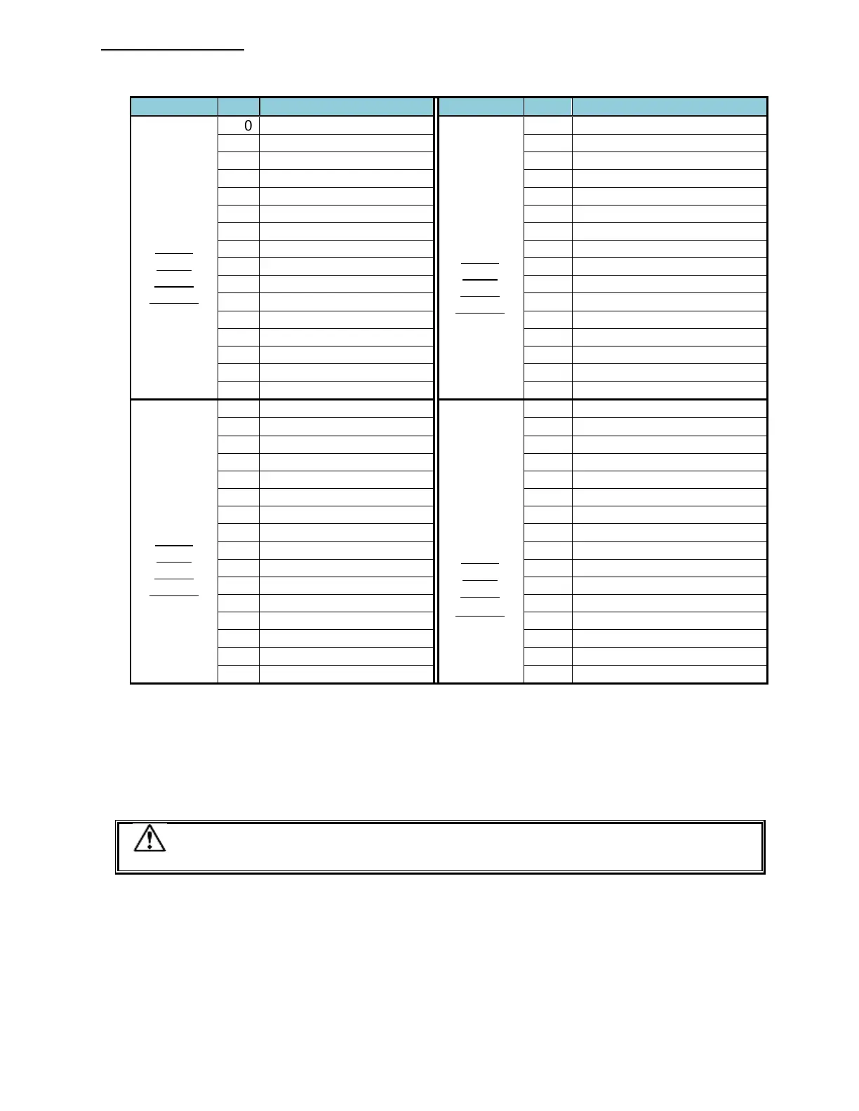
Output word
No. 5
Output
Signal
Setting
Example
Output word
No. 7
Output
Signal
Setting
Example
LO CUR LIMIT WARNING No.5
HI CUR LIMIT WARNING No.5
CURRENT WARNING No.5
CAL VOLTAGE WARNING No.5
ZERO VOLT WARNING No.5
JUDGE COMBO (BIT1) No.5
JUDGE COMBO (BIT2) No.5
JUDGE COMBO (BIT3) No.5
JUDGE COMBO (BIT4) No.5
JUDGE COMBO (BIT5) No.5
JUDGE COMBO (BIT6) No.5
JUDGE COMBO (BIT7) No.5
JUDGE COMBO (BIT8) No.5
Output word
No. 6
Output
Signal
Setting
Example
Output word
No. 8
Thru
No. 16
Output
Signal
Setting
Example
ST
ST
The example above (output word 5-7) shows an example of all available signals for each spindle.
While normally not all signals are used, any of the signals (for each spindle) can be preset
(programmed using the AFC3000 software) to any output bit.
* The word No. at the PLC input side differs according to the setting of the node address, etc., so please be
sure to confirm before using. Please refer to the AFC3000 Operation Manual, Section 5-3-2 and 5-3-3 for
description of the respective signals.
The unused area of Word 01 to 16 is also secured.
Caution
 Loading...
