MicroPulse MPSxxU Manual
2
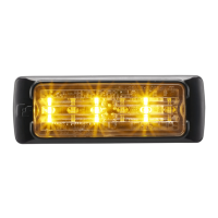
MPSxxU Light Head
Federal Signal www.fedsig.com
• Before drilling into a vehicle structure, ensure that both sides of the surface are clear of anything
that could be damaged. Remove all burrs from drilled holes. To prevent electrical shorts, grommet all
drilled holes through which wiring passes. Ensure that the mounting screws do not cause electrical or
mechanical damage to the vehicle.
• Because vehicle roof construction and driving conditions vary, do not drive a vehicle with a
magnetically mounted warning light installed. The light could fly o the vehicle, causing injury or
damage. Repair of damage incurred because of ignoring this warning shall be the sole responsibility
of the user.
• Locate the light system controls so the VEHICLE and CONTROLS can be operated safely under all
driving conditions.
• After installation, test the light system to ensure that it is operating properly.
• Test all vehicle functions, including horn operation, vehicle safety functions, and vehicle light systems
to ensure proper operation. Ensure that the installation has not aected the vehicle operation or
changed any vehicle safety function or circuit.
• Scratched or dull reflectors or lenses will reduce the eectiveness of the lighting system. Avoid heavy
pressure and the use of caustic or petroleum-based products when cleaning the lighting system.
• Replace any optical components that may have been scratched or crazed during system installation.
• Do not attempt to activate or deactivate the light system controls while driving in a hazardous
situation.
• Frequently inspect the light system to ensure that it is operating properly and that it is securely
attached to the vehicle.
• After installation and testing are complete, provide a copy of these instructions to instructional sta
and all operating personnel.
• File these instructions in a safe place and refer to them when maintaining and/or reinstalling the
product. Failure to follow all safety precautions and instructions may result in property damage,
serious injury, or death.
Introduction
The light head uses an LED light source to provide a reliable signal with 25 selectable flash patterns.
The light head may be flush mounted or attached to brackets. The light can operate on a nominal 12 or
24Vdc power source. A five-conductor cable protrudes from the base. This light head features FSLink
™
.
It can be synchronized with up to eight other FSLink products.
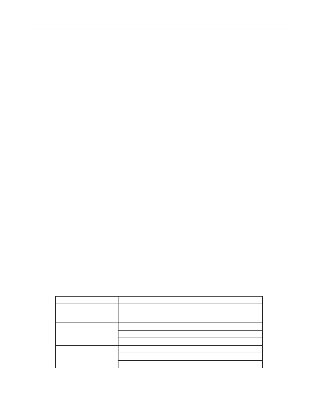
Table 1 Specications
Input Voltage 11 TO 28 Vdc
Nominal Current Draw MPS3U 0.4 A at 12 V, 0.2 A at 24 V
MPS6U 0.8 A at 12 V, 0.4 A at 24 V
MPS12U 1.5 A at 12 V, 0.8 A at 24 V
Dimensions (With Bezel) MPS3U 3.5 x 1.3 x 0.4 inches (8.89 x 3.30 x 1.02 cm)
MPS6U 5.2 x 1.3 x 0.4 (13.21 x 3.30 x 1.02 cm)
MPS12U 5.3 x 1.9 x 0.4 (13.46 x 4.83 x 1.02 cm)
Product Weight MPS3U 0.10 lb (0.05 kg)
MPS6U 0.13 lb (0.06 kg)
MPS12U 0.20 lb (0.09 kg)
 Loading...