Supply
Electronic Wattmeter
Chapter
2
The current-sensing circuit is in the lower line and should
be
connected
in
the neutral line. (This is good practice since it
keeps
low the operating potential of the wattmeter common
connection). However, if necessary, it is
possible to operate with
the upper
line at neutral. (This situation may occur where it is
not
possible to break the neutral line or where a dangerous
situation
would
be
created if the 1
OA
overload protective fuse
in
series with the current-sensing circuit were ruptured). The live
voltage
must not then exceed 280V with respect to ground.
With
conventional dynamometer wattmeters a decision has to
be made before connection whether to
include the internally
consumed watts of the current coils or the voltage coils
in
the
power
supply measured.
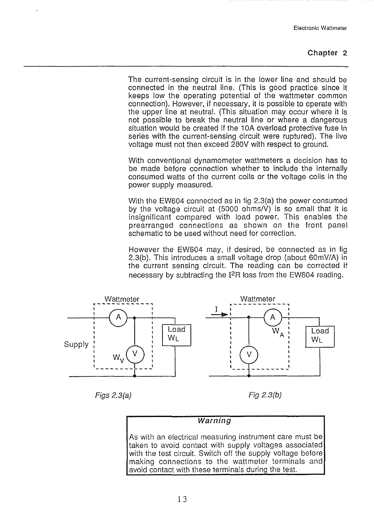
With the EW604 connected
as
in
fig 2.3(a) the power consumed
by the
voltage circuit
at
(5000 ohms/V) is
so
small that it is
insignificant compared with
load power. This enables the
prearranged connections as shown
on
the front panel
schematic to
be
used without need for correction.
However the EW604 may, if desired,
be
connected
as
in
fig
2.3(b). This introduces a small voltage drop (about 60mV/A)
in
the current sensing circuit. The reading can
be
corrected if
necessary
by
subtracting the
I2R
loss from the EW604 reading.
Wattmeter
'"
___________
,
Figs 2.3(a)
Load
WL
Wattmeter
... -----------,
I ' ,
__.,
l-r'----,
Warning
'
'
'
---
--------
Fig 2.3(b)
Load
WL
As
with
an
electrical measuring instrument care must
be
taken
to
avoid contact with supply voltages associated
with the test circuit.
Switch off the supply voltage before
making connections to the wattmeter
terminals and
avoid contact with these
terminals during the test.
1 3