Pin No.
1
2
3
4
5
6
7
8
9
10
1 1
12
13
14
Electronic Wattmeter
Chapter 4
AC
Transistor
AA
AD
AE
AF
array
-
+0.7
-7.4 -7.4 -7.4
-7.4
- +0.7 0 +0.7 +0.7 0
+22 0 0 +0.7 +0.7
0
0 +0.7
-7.5
-7.5
-7.5
-7.5
0 +0.7
-7.4 -7.4 -7.4
-7.4
-7.5
+0.7 +0.7 +4.7 0
0
-
0
+24
+24
+24 +24
- +0.7
-
-
-
-
-5.8
+0.7
-5.8
+0.7
+24 +0.7
+22 +0.7
-
0
- +0.7
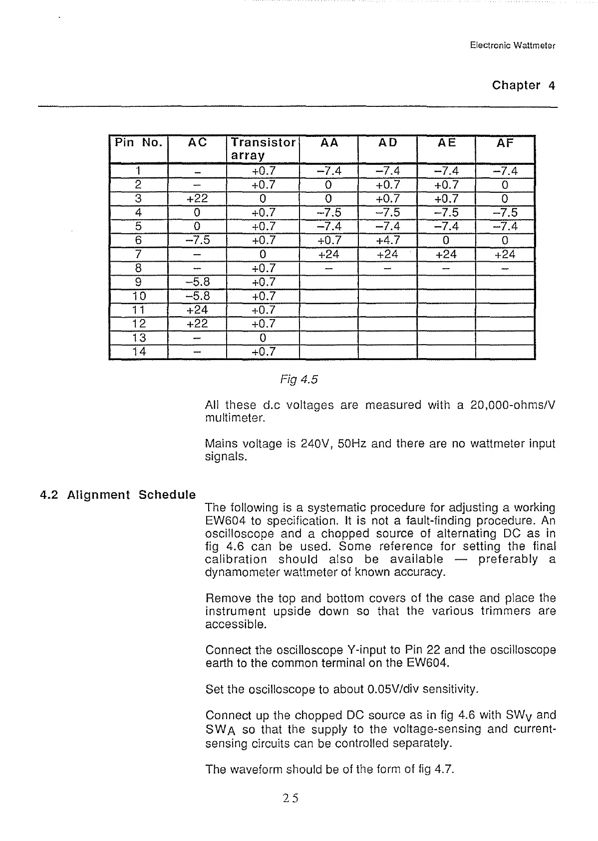
Fig 4.5
All these d.c voltages are measured with a 20,000-ohms/V
multi
meter.
Mains
voltage
is
240V, 50Hz and there are
no
wattmeter input
signals.
4.2 Alignment
Schedule
The following is a systematic procedure for adjusting a working
EW604 to specification. It is not a fault-finding procedure.
An
oscilloscope and a chopped source of alternating
DC
as
in
fig 4.6 can
be
used. Some reference for setting the final
calibration
should also be available - preferably a
dynamometer wattmeter of known accuracy.
Remove the top and bottom covers of the case and
place
the
instrument upside down
so
that the various trimmers are
accessible.
Connect the oscilloscope Y-input to
Pin
22
and the oscilloscope
earth to the common terminal
on
the EW604.
Set the oscilloscope to about 0.05V/div sensitivity.
Connect up the chopped
DC
source
as
in
fig 4.6 with SWv
and
SWA
so
that the supply to the voltage-sensing and current-
sensing circuits can
be
controlled separately.
The waveform
should
be
of the form of
fig
4.
7.
25