Electronic Wattmeter
Chapter 4
On
replacing the handle, press home the centre caps
and
then
rotate them until they
click into position.
The handle also acts
as
a stand and can be re-positioned
by
easing outwards the two ends simultaneously.
Positions of components and test points referred to in the
following text can
be
found by reference to the component
layout,
fig
4.2
and the complete circuit diagram
fig
4.3.
Faults
will show by inaccurate readings or by
no
sensible
reading at
all.
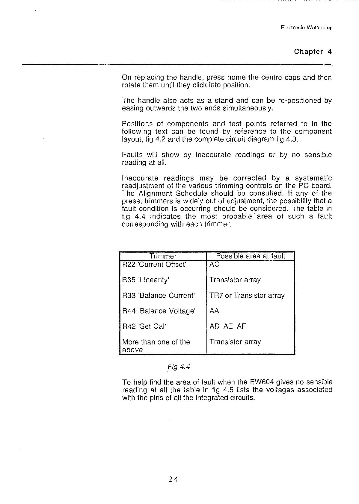
Inaccurate readings may be corrected by a systematic
readjustment of the various trimming controls
on
the PC board.
The Alignment Schedule should
be
consulted. If any of the
preset trimmers is widely out of adjustment, the possibility that a
fault condition is occurring should
be
considered. The table
in
fig 4.4 indicates the most probable· area of such a fault
corresponding with each trimmer.
Trimmer
Possible area
at
fault
R22
'Current Offset'
AC
R35
'Linearity' Transistor array
R33 'Balance Current'
TR? or Transistor array
R44 'Balance Voltage'
AA
R42
'Set Cal'
AD
AE
AF
More than
one
of the
Transistor array
above
Fig 4.4
To help find the area of fault when the EW604 gives
no
sensible
reading
at
all the table in fig 4.5 lists the voltages associated
with the pins
of
all the integrated circuits.
24