
M
Michelle TaylorAug 3, 2025
What to do if FeelElec FY6800 set correctly, but no waveform output?
- CChristy LyonsAug 4, 2025
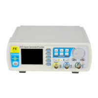
If your FeelElec Test Equipment isn't outputting a waveform even after you've configured it, here's what to check: 1. Ensure the BNC cable is securely connected to both the CH1 or CH2 connector and the test instrument. 2. Inspect the BNC cable for any internal damage. 3. Verify that the CH1 or CH2 indicators are illuminated. If not, press the corresponding button to activate the output.