STEP 3: ASSEMBLE ENDS
Note: Separate instructions are included in the tube cartons listed below
Twist, Lock and Hold EACH tube join before installing first screw.
Assembly for Tube Sets below require
24 self-drilling screws EACH.
Do not pre-drill holes or over-tighten screws.
80“ end tube 80“ end tube
Min. Insertion 16“ (40 cm)
Min. Insertion 16“ (40 cm)
L18/AG24EX* 2 1/2“ diameter tubes* Maximum Extension 24’ (7.3 m). Maximum Cover Weight 30# (13.6kg)
19“ joiner tube
90“ end tube
90“ center tube
90“ end tube
Min. Insertion 9“ (22.5 cm)
Min. Insertion 9“ (22.5 cm)
AGHD2 3“ diameter tubes8** Maximum Extension 28’6” (8.6 m). Maximum Cover Weight 40# (18.18kg)
90“ center tube (Extension tube)
19“ joiner tube
** Extra hardware, instructions and larger plugs are included in tube set carton.
** Extra hardware and instructions are inside extension tube.
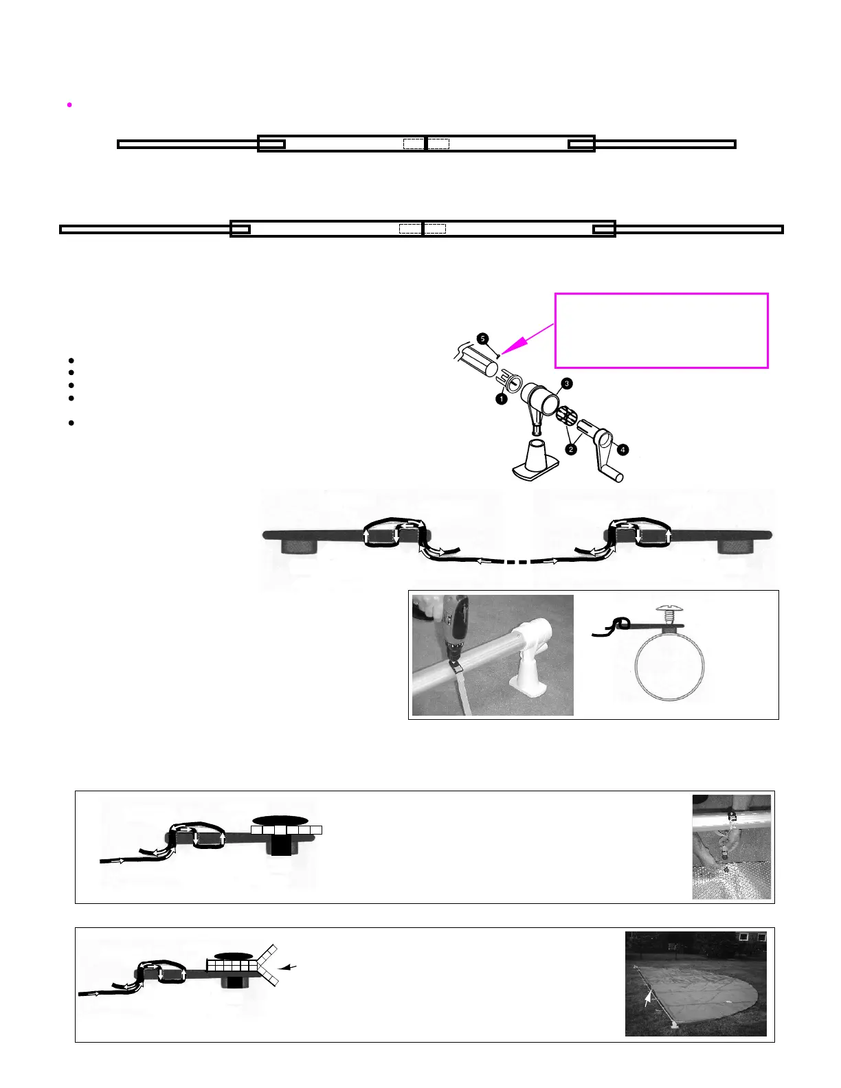
Assemble in numerical order (see Fig. 7):
Insert #1 Plug into End Tube.
Place #2 Bearing inside #3 Tee.
Push #4 Handle through Bearing and into Plug.
Repeat for other end.
Insert #5 self-drilling screw through tube in line with
a bump on plug rim and 1“ (2.5 cm) from tube end.
Fig. 6
FG-B-HAN - Handle
FG-BEA005 - Bearing
FG-TEE
FG-614 - Cone
FG-PLGL - Plug
IMPORTANT
Tube Assembly for L18/AG24EX or L18M/AG24EXM*(mill) and AGHD28
Insert #5 self-drilling screw through
tube in line with bump on plug
rim and 1“ (2.5 cm) from tube end. (at
BOTH ends)
80“ center tube 80“ center tube (Extension tube)
Strap end
Tube End
Strap Plate
Strap end
Fig. 8
Cover End
Strap Plate
Strap
STEP 4: STRAP ATTACHMENT - TO TUBES
A.
Tube
Fig. 9
Metal Self-Drilling
Screw
B.
For Reel Systems Placed at Pool End (Rectangular Pools) (Fig.10)
Cover
(bubbles
down)
Fig. 10
Plastic Screw
Fig. 11
For Reel Systems placed at Mid-Pool (Round or Irregularly Shaped Pools) (Fig. 11)
Strap end
Cover is
folded
“Pinched Fold”
(bubbles in)
Plastic Screw
Strap end
Choose the appropriate instructions below for your pool setup. If you have determined a mid-pool placement, it will be easier if you move the
cover away from the pool and fold it (bubbles in) on a flat surface. Choose EITHER Fig. 10 OR Fig. 11.
C.
Strap Plate
Strap Plate
Mark each end tube 6“ (15 cm) in from the inside edge
of top rail of pool. Strap plates are spaced evenly between
these marks. Mark strap plate locations along drill lines.
Use all straps provided.
Attach strap plates to tube (see Fig. 9). DO NOT pre-drill holes or
over-tighten screw.
Strap
Plate
with
Strap
STRAP ATTACHMENT - TO COVER
Fold cover where system will be placed
(bubbles in). Pierce hole through both sides of
cover, 1“ (2.5 cm) back from the fold and
straight down (perpendicular) from a strap plate
already attached to tube. Push threaded plastic
screw through holes in cover then tighten
snugly into plate. Repeat for remaining straps.
Pierce hole through cover, 1“ (2.5 cm) back from
edge of cover and straight down (perpendicular)
from a strap plate already attached to tube.
Push threaded plastic screw through hole in
cover then tighten snugly into plate. Repeat for
remaining straps.
STEP 4: STRAP ATTACHMENT
Attach a Strap Plate to EACH
end of all Straps provided
(see Fig. 8).
Fig. 7
Place straps evenly
along fold.
Pinched fold
(Butt center tubes)
(Butt center tubes)
* Mill tubes may tarnish over time. Anodized tubes help reduce tarnishing.
 Loading...