ACOUSTASONIC JUNIOR
THEORY OF OPERATION
INSTRUMENT CHANNEL (cont)
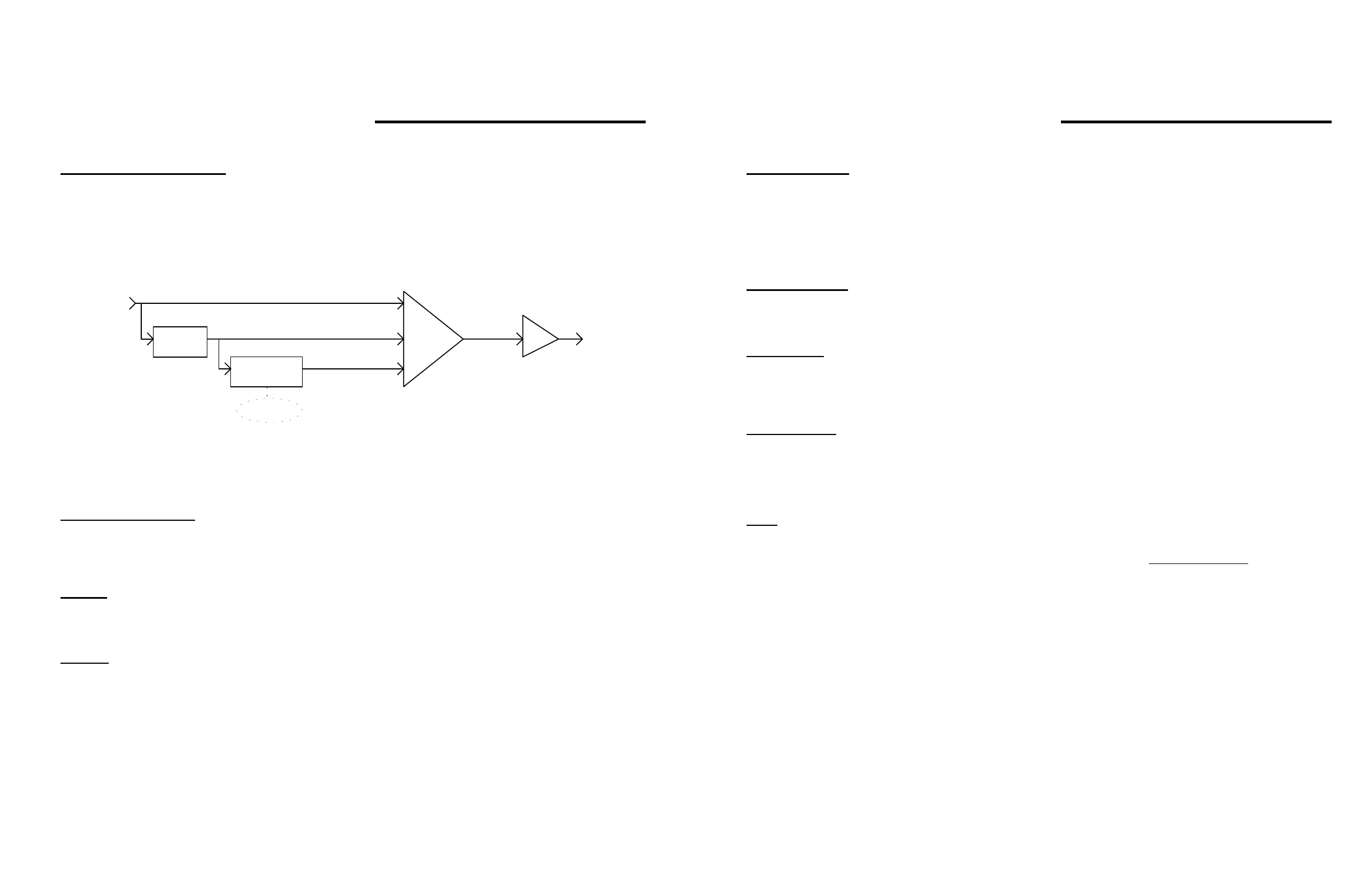
The String Dynamics function (Fig. 2) is the summation of three signals:
1) The original audio signal from U2B-7,
2) The bandpass amp, U4A-1, and
3) The notch control circuit comprised of operational transconductance amplifier, U5A,
op. amps, U6A&B, and potentiometer, R40
Σ
Audio In
Define
Frequency
amplitude control
String
Dynamics
Audio
R36
R37
R38
U4B
U4A
U6A-B, U5A
(Fixed bandpass)
Invert bandpass & add
Fi
namics function
c) A Mono-Effects Loop allows effects to be used on the instrument channel without affecting the
signal from ch. 2.
MICROPHONE CHANNEL
The Microphone Channel (ch. 2) can also be used as a second instrument or line-input channel. It, too, is designed
with operational amplifiers. Phantom power is present at the mic jack. The phase of channel 2 can be reversed with a
push-button switch.
REVERB
The Reverb circuit is typical of solid-state reverb circuits, except that the Reverb send from the Microphone Channel
has a separate control allowing individual adjustment for that channel.
CHORUS
The Chorus circuit is typical of Fender's chorus circuits in which the raw signal from U12-1 is shifted down a bucket-
brigade, U13, by pulses from a shift-register, U15.
The chorus is turned on and off by a master chorus in/out button. This button is completely non-functional if the
Footswitch is plugged in (the one-and-only function of the Footswitch is master chorus off/on.)
ACOUSTASONIC JUNIOR
THEORY OF OPERATION
SWITCHING LOGIC
The Switching Logic accomplishes several functions:
a) It switches the chorused signal to the right power amp, while leaving the clean signal on the left
power amp;
b) It allows for the separate selection of reverb for channel 1;
c) It allows for separate selection of chorus for channel 2.
STEREO BUFFERS
The Stereo Buffers (left: U10A, right: U10B) route the L & R signals to the Stereo EFX Loop. Following the loop is
S5, which will switch the phase of both signals 180°.
POWER AMPS
The Power Amps are a traditional Fender design with no bias and/or offset adjustments. The input is made through a
differential pair, Q11/Q12 L (Q21/Q22 R). An interesting addition is the pwr up/dwn quieting circuit (Q10) which cuts
off the differential pairs through their emitter circuit while power is first turned on, or turned off.
POWER SUPPLY
The Power Supply is a bridge rectifier type which supplies +/- 39 V for the power amp rails; this is dropped to
approximately 16 V and regulated with 7815 & 7915 regulators to provide the +/- 15 V for the IC's. An LED on the front
panel serves as a power indicator.
NOTE
Please notice that the output power measurement as stated on the schematic for this product is stated slightly different
than other products. It says that for a given input (640 mV, 1 kHz) inserted at the stereo effects return (J6), the output
of each power amp should not be less than 40 Watts @ 0.2% THD into an 8Ω resistive load, with both channels
driven.
The signal path through the amp still has signal (AC ) measurements shown in ovals to assist in determining relative
gains through the stages.






 To Next Page