Do you have a question about the Fender Super Champ-XD and is the answer not in the manual?
Explains bypassing the DSP board and creating a tone control for the Fender Super Champ XD amplifier.
Details required technical skills, tools like soldering iron, heat gun, and multimeter for the modification.
Emphasizes the importance of reading instructions and wearing protective eyewear before starting.
Lists required resistors (10k ohm) and capacitors (.03uF, 4.7/5.0uF) with voltage ratings.
Specifies hookup wire, heat shrink tubing, tie wraps, and optional label maker.
Instructions for unplugging power/speaker, removing chassis, and orienting the circuit board.
Detailed steps on cutting PCB traces around R85 (VOLUME) and R84 (GAIN) as per schematic.
Guidance on cutting and insulating specific conductors (#1, #2, #3, #8) on the ribbon cable.
Describes connecting wires and components to specific pins (P5 pin 11, 5, 13, 1) on connector P5.
Details the wiring steps for connecting components to terminals A, B of R85 and R52.
Details the wiring steps for connecting components to terminals A, B, and C of R84.
Instructions for capacitor connections, securing wires, and reassembling the chassis into the cabinet.
Provides a schematic diagram illustrating the modified circuit with red indicators for changes.
Presents measured frequency response data for the amplifier in FLAT and BRIGHT modes.
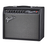
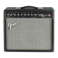
This document outlines a detailed procedure for modifying a Fender Super Champ XD amplifier, specifically to bypass its Digital Signal Processor (DSP) board. This modification is primarily intended for situations where the digital section of the amplifier is malfunctioning, while the analog (tube) portion remains operational. It also applies to similar amplifiers like the Vibro Champ XD.
The core function of this modification is twofold: first, to completely remove the DSP board from the amplifier's circuit, and second, to re-purpose existing controls to create a functional tone adjustment, as the original tone control was integrated into the DSP board. Specifically, the R84 ("GAIN") and R85 ("VOLUME 1") potentiometers are re-assigned to new functions. Upon completion, the amplifier will offer VOLUME and BRIGHTNESS (TONE) adjustments. The modification assumes that the user wishes to retain the characteristic "tube amp" sound and plans to introduce any desired effects externally, between the instrument output and the amplifier input.
The document emphasizes the importance of verifying the condition of the amplifier's tubes and checking for other common issues like disconnected speaker wires or blown fuses before attributing problems to the DSP board. This diagnostic step ensures that the modification is indeed necessary and addresses the root cause of any issues.
For maintenance and reliability, the instructions are meticulously detailed, requiring good workmanship and soldering skills. The necessary tools include a low/medium power soldering iron, a heat gun, a Dremel-type cutting tool or X-Acto knife, and an ohm-meter/multimeter for verifying cuts in PCB traces. Safety is also highlighted, with a reminder to wear protective eyewear.
The step-by-step instructions begin with crucial safety precautions, such as unplugging AC power and speaker cables. The process involves disassembling the chassis from the cabinet, but explicitly states not to remove any printed circuit boards from the chassis itself. Users are advised to handle tubes carefully, with an option to remove them for safety. The orientation of the chassis and the "Breakaway" board (which houses the controls) are clearly illustrated to guide the user.
A key step involves unplugging and setting aside the ribbon cable from P5 and the DSP board, as these components will no longer be used. The modification then proceeds to the "Breakaway" board, where specific thru-hole points (A, B, C) related to R84 (GAIN) and R85 (VOLUME 1) are identified. The instructions guide the user to make precise cuts in the PCB traces associated with these potentiometers. After each cut, it is imperative to use an ohm-meter to confirm that the trace is indeed "open" (indicating a successful cut) and not still conductive (zero ohms).
Further steps involve modifying the ribbon cable PW3 by cutting specific conductors (#1, #2, #3, and #8) and insulating them with heat-shrink tubing (HST). This ensures that these conductors, which previously connected to the DSP board, are isolated and do not interfere with the new circuit.
The modification then details the installation of new components. This includes connecting a bare wire from P5 pin 11 to P5 pin 5 (AGND). A 4.7 or 5.0 µF capacitor is integrated into the circuit, with specific instructions on trimming its lead, tinning, soldering it to P5 pin 13, and insulating the connection with HST. Following this, a 10K resistor is connected to the free end of the capacitor, again with precise instructions for trimming, tinning, soldering, and insulating with HST. Another bare wire is then connected from the 10K resistor to P5, Pin 1, with careful attention to HST placement to avoid heating during soldering.
The wiring to R85 is meticulously described, involving cutting and stripping wires to specific lengths, then soldering them to terminal C of R85, the left end of R52, and terminals A and B of R85.
A crucial part of the tone control implementation is the creation of a .03 µF capacitor. The document provides two methods for this: either by soldering a .01 µF and a .02 µF capacitor in parallel, or by soldering three .01 µF capacitors in parallel. Clear illustrations are provided for both combinations.
The wiring to R84 follows a similar detailed approach. A wire is cut, stripped, and bent, then tinned along with the three terminals of R84. One end is soldered to the bare wire between the 10K resistor and P5, pin 1. The other tinned end is soldered to terminals A and B of R84. Finally, one lead of the newly created .03 µF capacitor pair is covered with HST and soldered to terminal C of R84. The other end of the capacitor pair is trimmed to reach a specific jumper point between J5 pin 5 and J5 pin 11, formed into a hook, clamped, and soldered, with all connections insulated with HST. The document explicitly notes that if the .03 µF cap doesn't reach, additional wire should be added.
To ensure the long-term reliability and stability of the modification, the instructions advise tying off the flying components and wires with lacing twine or cable ties at designated points. This prevents accidental disconnections or short circuits due to vibration or movement.
The final steps involve reassembling the chassis into the cabinet in reverse order. A critical reminder is given to ensure all components and wires are positioned below the chassis edges to prevent contact with the cabinet, especially considering the cabinet's foil lining in the chassis area.
The document concludes with an example of how the front-panel controls can be re-labeled to reflect their new functions (e.g., "VOLUME" and "FLAT BRIGHT VOLUME"). Appendices provide a schematic showing all the changes made and frequency response data, illustrating the effect of the new Brightness Control. The frequency response data indicates that with the FLAT/BRIGHT dial at "1," the output at the speaker terminals varies less than 3dB from 70 Hz to 7kHz, providing a clear understanding of the sonic characteristics of the modified amplifier. This comprehensive guide ensures that even a complex modification can be performed successfully, resulting in a reliable and great-sounding Fender tube amp.
| Type | Hybrid |
|---|---|
| Power | 15 Watts |
| Preamp Tubes | 1 x 12AX7 |
| Power Tubes | 2 x 6V6 |
| Inputs | 1 x 1/4" |
| Speaker | 10" Fender Special Design Speaker |
| Channels | 2 |
| Effects | Reverb, Delay, Chorus |
| Outputs | 1 x 1/4" |
| Dimensions | 17.5" |
| Weight | 24 lbs |