EasyManua.ls Logo

Fenwal Controls 35-9 Series - User Manual

Fenwal Controls 35-9 Series
13 pages
Print Icon
To Next Page IconTo Next Page
Loading...
F-35-2000
October 2018
1 of 12
Series 35-9X Modulating
Platform Ignition Module (PIM
®
)
OPERATION AND INSTALLATION INSTRUCTIONS
DESCRIPTION
The Fenwal Controls Platform Ignition Module (PIM
®
) integrates
the functions of Automatic Ignition Control with temperature
regulating and control functions. The PIM is designed for a range
of hydronic boilers including both staged systems and
modulating types. The PIM can be configured as a direct spark
ignition (DSI), intermittent pilot (IP) or Hot Surface Ignition
(HSI) to provide safe lighting and supervision of the burners in
an appliance. The PIM is also designed to connect to and receive
commands from the tekmar
®1
Host Controller. When connected
to a Host Controller, the PIM offers expanded control
functionality including Domestic Hot Water, outdoor reset,
diagnostic messages, and other system capabilities.
APPLICATIONS
The PIM and Host Controller system is suited to a wide variety
of gas-fired hydronic heating systems including:
High-efficiency Modulating Condensing Boilers
Fan-assisted single and multi-staged Boilers
Multiple Boiler Installations using intelligent sequencing
Intermittent Pilot based Hydronic appliances
Water Heaters
Pool and Spa Heaters
AGENCY APPROVALS
SPECIFICATIONS
1.The tekmar BTCII Boiler Controller is fully compatible with
the Fenwal PIM and provides complete hydronic boiler
operation. For more information, contact tekmar controls at
(250) 545-7749.
2. EMC Emission testing to be verified after incorporation into
end use appliance.
CSA Design certified to ANSI Z21.20,
CAN/CSA C22.2 No. 199-M99 and ANSI
Z21.20-2014 CAN/CSA C22.2 No.
60730-2-5-14
CE Approved to EN 298-2012
2
WARNING
Installing or operating the product inconsistent
with these instructions or specifications could
cause serious property damage, injury or death.
Specification Value
Input Power Control: 18-30 VAC 50/60 Hz
(Class 2 Transformer)
Input Current Drain 400 mA @ 24 VAC with gas and
blower relays energized (Control
only)
Gas Valve Relays 5.0A max (continuous)
Combustion Blower 5.0 A max for standard (J2)
connection
15.0 A max for heavy-duty (K5
relay) terminals
Hot Surface Igniter 5.0 A max, 120/240 VAC
Pump Relays 5.0 A max (continuous)
Alarm Relay 2.0 A, 30 VDC or 30 VAC max
Operating Temperature -40°F to + 165°F (-40°C to +74°C)
Storage Temperature -40°F to + 185°F (-40°C to +85°C)
Sensor Temperature Range -22°F to + 260°F (-30°C to
+126°C)
Flame Sensitivity 0.7 μA minimum
Flame Failure Response or
Reignition Time
0.8 seconds maximum
Flame Detector Self-check Rate Once per second minimum
Flame Failure Lockout Time Varies by model
Types of Gas Natural, LP, or manufactured
Spark Rate Remote sense (50/60 Hz)
Local sense (25/30 Hz)
Size (LxWxH) 8.50 x 6.50 x 2.50 inches
(21.59 x 16.51 x 6.35 cm)
Ingress Protection Not rated, protection provided by
appliance in which it is installed.
Moisture Resistance Conformal coated to operate non-
condensing to 95% R.H.
Tries for Ignition One or three try versions available
Trial for Ignition Period 1 to 30 seconds, up to 300 seconds
(IP)
Pre-purge Timings 1 to 255 seconds
Inter-purge Timings 1 to 255 seconds
Question and Answer IconNeed help?

Do you have a question about the Fenwal Controls 35-9 Series and is the answer not in the manual?

Overview

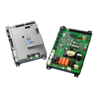
The Fenwal Controls Series 35-9X Modulating Platform Ignition Module (PIM) is a sophisticated control system designed for gas-fired appliances. It integrates various functions to manage ignition, combustion, and overall system operation, offering flexibility for both standalone and Host Controller-driven applications.

Function Description

The PIM serves as a central control unit for gas ignition and combustion processes. It manages the sequence of operation from standby to heat call, including pump purging, blower prepurge, and ignition. The module supports different ignition types, including Direct Spark Ignition (DSI), Hot Surface Ignition (HSI), and Intermittent Pilot Ignition (IPI), making it adaptable to various appliance designs.

In standalone mode, the PIM's operating parameters can be adjusted via a potentiometer for outlet water temperature, with settings ranging from 110°F to 210°F. When connected to a Host Controller, the PIM communicates via an RS485 bus, allowing the Host Controller to manage system operation and firing rates. This enables advanced features like outdoor reset and DHW functions based on sensor inputs.

The PIM utilizes an Identification Card (ID Card) to determine its operating parameters. This card contains unique codes (up to 126 supported) that select specific settings for ignition timings, operation, and OEM configuration. The PIM stores these settings in non-volatile memory upon first power-up with a valid ID card and verifies the card at each power-up. If the ID card is not present or does not match the stored settings, the PIM will not operate.

The module incorporates an 8-position DIP switch for field-configurable items such as operator differential, analog input type, pump post purge, pump exercise enable, EMS/demands, EMS signal type, freeze protection, and commission test. These settings allow for customization to specific application requirements.

Important Technical Specifications

Electrical Ratings:

  • Input Voltage: 24 VAC (18-30 VAC operating range)
  • Gas Valve Relays: 5.0 A max (continuous)
  • Combustion Blower: 5.0 A max for standard (J2) connection, 15.0 A max for heavy-duty (K5 relay) terminals
  • Hot Surface Igniter: 5.0 A max, 120/240 VAC
  • Pump Relays: 5.0 A max (continuous)
  • Alarm Relay: 2.0 A, 30 VDC or 30 VAC max
  • Spark Output (T3 coil): 25 kV
  • Hot Surface Element: 5.0 A Max

Temperature Ranges:

  • Operating Temperature: -40°F to +165°F (-40°C to +74°C)
  • Storage Temperature: -40°F to +185°F (-40°C to +85°C)
  • Sensor Temperature Range: -22°F to +260°F (-30°C to +126°C)

Timing Specifications:

  • Flame Sensitivity: 0.7 µA minimum
  • Flame Failure Response or Reignition Time: 0.8 seconds maximum
  • Flame Detector Self-check Rate: Once per second minimum
  • Flame Failure Lockout Time: Varies by model
  • Trial for Ignition Period: 1 to 30 seconds, up to 300 seconds (IPI)
  • Pre-purge Timings: 1 to 255 seconds
  • Inter-purge Timings: 1 to 255 seconds

Sensor Compatibility:

  • Thermistors: Standard support for 10K ohm @ 77°F NTC curve J Thermistor probes (β=3892). Optional 12K ohm thermistors are available.
  • Analog Input: 0-10 VDC or 4-20 mA from an Energy Management System.

Dimensions (LxWxH): 8.50 x 6.50 x 2.50 inches (21.59 x 16.51 x 6.35 cm)

Usage Features

The PIM offers a comprehensive set of features for controlling gas-fired appliances:

  • Integrated UL353 High Limit: Utilizes a thermistor sensor for high-limit protection.
  • Configurable Parameters: Settings are selected via a unique ID Card, ensuring correct configuration for specific appliance models.
  • Host Controller Communication: Communicates via RS485 with a Host Controller, supporting tN4 signals for enhanced system integration.
  • Temperature Measurement: Measures Inlet, Outlet, Limit, and Vent temperatures using NTC curve J Thermistors.
  • External Sensor Inputs: Optional signals from DHW, System, and Outdoor Air sensors can be sent to the Host Controller for outdoor reset and DHW functions.
  • Energy Management System (EMS) Support: Accepts external 0-10 VDC or 4-20 mA inputs from an EMS.
  • Pump and Blower Control: Controls Boiler, System, and DHW pumps, as well as the combustion blower speed (PWM output or 4-20 mA signal) with closed-loop RPM control via tachometer feedback.
  • Ignition Control: Supports Hot Surface, Direct Spark, and Intermittent Pilot Ignition (single stage only). Allows for external HV transformer.
  • Safety Features: Includes low-voltage detection and safe shutdown below 18.0 VAC, fail-safe control for one or two stages of gas valves, and monitoring of airflow, water flow, and gas pressure switches.
  • Diagnostics: Provides system and control diagnostics via on-board or remote LED, communicating diagnostic status to the Host Controller.
  • Automatic Reset: Optional automatic reset after ignition lockout (one hour or as defined).
  • Flame Sensing: Supports local (through HSI or DSI element) or remote flame sensing, with full-time flame sensing.
  • CSD-1 Compliance: Configurable to meet CSD-1 applications.
  • Manual Reset: For ignition lockout or hi-limit conditions.
  • Field Test/Pump Exercise Capability: Allows for testing and pump exercise.
  • Alarm/Alert Output: Dry contact relay output for alarm and alert conditions.
  • Multi-stage Gas Valve Support: Capability for two PIMs to support up to 4 gas valve stages using a master/member configuration.

Maintenance Features

  • LED Indicators: Three LED indicators (Power, Alarm/Test, Diagnostic Code) provide operational status and aid in diagnosing system error conditions.
    • Power (Green): Indicates 24 VAC power is supplied to the PIM.
    • Alarm/Test (Amber): Indicates Commission Test Mode or a diagnostic alarm/fault.
    • Diagnostic Code (Red): Flashes error codes during control or system fault conditions, with a detailed LED error code listing for troubleshooting.
  • Troubleshooting Guide: The manual provides a comprehensive LED error code listing with recommended troubleshooting steps for various faults, including ID Card Fault, Internal Control Failure, Airflow Fault, False Flame Error, Ignition Lockout Fault, Low Voltage Fault, Sensor Faults, and Communication Faults.
  • ID Card Management: The ID card must remain with the appliance for its entire service life. In case of ID Card failure, replacement must be performed by a qualified technician with an ID card of the same number. ID Cards cannot be interchanged between appliances. If a PIM needs to be re-configured for a different ID card, its internal ID card settings must be cleared, requiring contact with the manufacturer for the reset process.
  • Wiring Diagrams and Tables: Detailed wiring diagrams for DSI and HSI configurations, along with comprehensive wiring tables for low-voltage and line-voltage connections, facilitate proper installation and maintenance.
  • Mounting Guidelines: The PIM enclosure is designed for mounting within an appliance's control box, either vertically or horizontally, using four #8 sheet metal screws. It is crucial to protect components from water exposure.
  • Wiring Requirements: All wiring must comply with local and national electrical codes, using at least #18 AWG rated for 105°C or higher.
  • High Voltage and Remote Sense Cable Requirements: Specific requirements are outlined for HV Ignition Cable (25 KV, 200°C, 3ft max) and Remote Flame Sense Cable (250V, 200°C, 10ft max), with recommendations to consult the factory for longer lengths.

Fenwal Controls 35-9 Series Specifications

General IconGeneral
BrandFenwal Controls
Model35-9 Series
CategoryControl Unit
LanguageEnglish