EasyManua.ls Logo

Fenwal 35-65 Series - User Manual

Fenwal 35-65 Series
8 pages
Print Icon
To Next Page IconTo Next Page
Loading...
#$!"
n
Safe start and full-time flame sensing
n
120/240 field selectable line voltage for use
with 120 VAC ignitor option
n
24/120/240 VAC hot surface ignitor models available
n
Blower control and airflow switch monitoring option
n
Diagnostic LED
n
Multiple trials for ignition
n
Automatic reset option
n
Local or remote flame sensing
n
Flame current test pins
n
Dual speed blower option for LoNox applications
n
Fail-safe gas valve control (35-66 only)
n
CE models available
#"
n
Pool and spa heaters
n
Gas furnaces
n
Water heaters
n
Any 24 VAC gas burner application under 400K BTU
"!#
The Series 35-65 and 35-66 controls are designed to perform many
gas-fired 24 VAC appliance functions in a single control, resulting
in lower system cost. This series monitors the demand for heat,
controls the combustion blower, monitors proper airflow, ignites and
maintains the flame during heating, and provides diagnostic support.
The on-board diagnostics with LED output provide assistance with
troubleshooting and ensures safe and efficient burner operation.
The microprocessor circuit design provides precise, repeatable
timing sequences for ignition and purge times (pre-, inter-, and post-)
as well as multiple tries for ignition. The optional 120/240 VAC field
selectable line voltage capability provides additional field service
efficiency and lower inventory costs.
Agency Certifications
Design certified by CSA International to
CAN C22.2 #199-M89 and ANSI Z21.20
for Automatic Ignition Systems, including
UL1998 software review. FM approval
and CE pending on selected models.
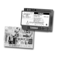
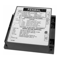
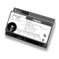
SERIES 35-65 & 35-66
24 VAC Microprocessor Based HSI Control
with 120/240 Field Selectable Line Voltage Capability
www.fenwalcontrols.com 1-800-FENWAL-1
Series 35-65, -66 HSI Control with 120/240 Field Selectable Line Voltage Page 1
35-65,-66.02
 "
!2/5%+)
633)15
  
%4!%/7)
20&645-21/28)3
2()/21/9
2563*%')/)0)15
 
!#
#

 
 
$" 
"
Control: 18 to 30 VAC 50/60 Hz
(Class 2 Transformer)
Line: 24, 120 or 240 VAC
(L1 & L2 only)
300 mA max @ 24 VAC with blower and gas
valve relay energized (Control only)
2.0A max @ 24 VAC
3.0 FLA max @ 120 VAC (1/4 hp)
1.5 FLA max @ 240 VAC (1/4 hp)
5.0A max @ 120/240 VAC
-40ºF to +176ºF (-40ºC to +80ºC)
0.7 microamps minimum
Natural, LP, or manufactured
24 VAC, 120 VAC, or 240 VAC
mini-ignitors and silicon carbide ignitors
depending on model
Gray (Noryl N-190)
Conformal coated to operate non-condensing
to 95% R.H. Care must be taken to protect
module from direct exposure to water
See Figures on Page 7
8 oz including cover
"#"
®
DS 35 65 66:DS 35 65 66.qxd 9/27/2010 9:08 AM Page 1

Questions and Answers

  • S
    Samantha SmithAug 3, 2025
    What to do if Fenwal 35-65 Control Unit does not start?
    • I
      Isabella HumphreyAug 3, 2025
      If the Fenwal Control Unit doesn't start, the issue might stem from several causes. First, check the wiring connections to ensure they are correctly configured. A faulty 24 VAC transformer could also be the culprit, requiring a replacement. Examine the fuse or circuit breaker and replace it if it's bad. Lastly, the control itself could be malfunctioning; inspect it and observe the LED indicators for any steady on or flashing codes.
  • Z
    Zachary PadillaAug 9, 2025
    Why is there flame okay during tFI but no flame sense after tFI in my Fenwal 35-65?
    • J
      John MilesAug 9, 2025
      If the Fenwal Control Unit exhibits a flame during tFI but loses flame sense afterward, several factors could be responsible. A defective ignitor might be the cause, so consider replacing it. Inspect the S1 wire for any damage and replace it if necessary. Ensure there's a solid ground connection at the burner. Also, verify that the flame current is adequate by measuring it to ensure it's at least 1 microamp. A poor flame can cause this issue.
  • A
    aaron77Aug 15, 2025
    What to do if thermostat is on but there is no ignition in Fenwal 35-65?
    • R
      Rachel LambertAug 15, 2025
      If your Fenwal Control Unit's thermostat is on but there's no ignition, start by checking the wiring connections to ensure they are correct. Test the thermostat for proper voltage, as a bad thermostat might not be sending voltage to terminal W. Finally, a failed ignitor could be the cause; in that case, you'll need to replace it.
  • K
    Krystal WhiteAug 20, 2025
    What to do if ignitor is on but there is no valve in Fenwal Control Unit?
    • J
      John SchultzAug 21, 2025
      If the ignitor is on, but the valve isn't activating in your Fenwal Control Unit, check the valve coil for continuity. Also, inspect the valve wiring for any breaks. If those aren't the problem, measure the voltage at the gas valve terminal, as there might be an issue with the control itself.
  • J
    jennifer83Aug 27, 2025
    How to troubleshoot valve on but no ignitor in Fenwal Control Unit?
    • J
      Jared ArnoldAug 27, 2025
      To troubleshoot a situation where the valve is on but the ignitor isn't working in your Fenwal Control Unit, start by replacing the ignitor, as it might be defective. Check the wiring connections to ensure they are properly connected. Inspect the control and measure the voltage at the ignitor to identify any issues with the control itself.

Summary

Features

Applications

Description

Agency Certifications

Specifications

Sequence of Operation

Call for Heat

Describes the sequence for calling for heat, including self-check, ignitor energization, and trial for ignition.

Failure to Light - Lockout

Details the control's response to the burner failing to light or flame detection during the trial for ignition period.

Loss of Flame - Re-ignition

Explains how the control handles loss of flame signal during operation, including re-ignition attempts and lockout.

Combustion Air Flow Problems

Specific to 35-66 models, this section details airflow monitoring via pressure switch and fault conditions.

Fault Conditions

Mounting and Wiring

Troubleshooting Guide

Flame Sensor Current Check

Control Wire Harness

Remote Flame Sense Rods

Wiring Diagrams

Series 35-65

Provides wiring diagrams for the Series 35-65 control, including local and remote flame sensing.

Series 35-66

Provides wiring diagrams for the Series 35-66 control, including local and remote flame sensing.

Dimensions

Control Configuration

Fenwal 35-65 Series Specifications

General IconGeneral
BrandFenwal
Model35-65 Series
CategoryControl Unit
LanguageEnglish

Related product manuals