6
EN
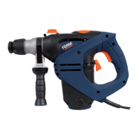
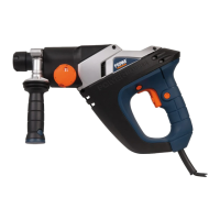
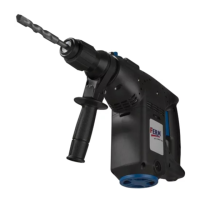
Description
The numbers in the text refer to the diagrams on
pages 2-3
Fig. A
3. Speed adjustment wheel
4. Lock-on button
5. Function selection switch
6. Side handle
7. Locking sleeve
8. Depth stop ruler
3. OPERATING
Hammer drills require very little operator
pressure. Excessive pressure on the tool
can lead to unnecessary overheating of
the motor, and burning of the driven tool.
It also may happen the drill bit deforms
and cannot be removed from the
machine again.
Side handle
Fig. A
The side handle (6) can be rotated 360° around
the drill head, enabling safe and comfortable
operation for both left and right-handed users.
• Loosen the handgrip by turning it
anticlockwise.
• Rotate the handgrip to the desired position.
• Retighten the handgrip in the new position by
turning it clockwise.
Exchanging and removing drill bits
Fig. A - B
Before exchanging bits, first remove the
power plug from the wall socket.
Inspect bits regularly during use. Blunt
bits should be re-sharpened or replaced.
• Lightly oil the bit shaft before inserting it into
the chuck.
• Slide the locking sleeve (7) to the rear and
insert the bit into the chuck opening. Ensure
that the keyway in the bit is seated properly
in the chuck by carefully turning the bit until it
clicks into place. After that release the locking
sleeve.
• To remove the bit, slide and hold the locking
sleeve to the rear.
Setting depth stop
Fig. A
• Loosen the handgrip by turning it
anticlockwise.
• Insert the depth stop ruler (8) through the hole
in the side handle ring.
• Slide the ruler to the desired depth.
• Retighten the hand grip firmly by turning it
clockwise
The On/Off switch
Fig. A
(2) the machine will turn off.
• The rotation-speed can be continuously
deeper or less deep.
Lock-on button
Fig. A
Off switch (2) and then pressing the lock-on
button (4).
• Release the switch-lock by shortly pressing
Adjusting of the maximum rotation speed
Fig. A
switch (2).
lock-on button (4).
• Adjust the speed by turning the speed
adjustment wheel (3) to the desired maximum
rotation speed.
Switching the direction of rotation
Fig. A.
• Direction of rotation counter-clockwise: shift
”.
”.
This function is only available when the machine