GB
9
A trial pass, with the router turned OFF
and the router bit not turning, is strongly
recommended.
• Warning!Neverleavetheroutertable
unattended while the router is running. Turn
the router OFF before leaving the router table
for any reason.
Always check that the power supply
corresponds to the voltage on the rating
plate.
Immediately throw away old cables or plugs
when they have been replaced by new ones. It is
dangerous to insert the plug of a loose cable in
the wall outlet.
Only use an approved extension cable suitable
for the power input of the machine. The minimum
conductor size is 1.5 mm
2
. When using a cable
reel always unwind the reel completely.
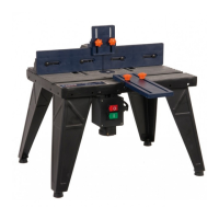
Fig. 1 - 13
Before assembling the table, ensure all
components are present. In case of
shortages please contact the service
address on the warranty card.
To assemble your router table, do the following:
• Laythetabletop(1,Fig.1)upsidedownona
flat surface (Fig.2).
• Placeatableleg(2,Fig.1)usingfourhex
head bolts (M6X12) and nuts (M6), do not
fully tighten yet (Fig.3).
• Repeattheabovefortheotherthreelegs,and
make sure the four legs are on the same flat
surface, then tighten all the bolts.
• Onceallfourlegsaresecurelytightened,turn
assembly over, check the table assy does not
rock. If any rocking is detected, this must be
rectified before continuing by loosening the
bolts on the offending leg/legs and adjusting
accordingly.
• Inserttwocoachbolts(M5X50)intoholes
marked “B” from the top of the table (Fig.4).
• Attachthefence(9,Fig.1),usinghexhead
bolts, washers and knobs supplied. Insert the
bolts from the underside of the table through
the holes marked “A” (Fig. 5). Place the
fence on the bolts and secure in position with
washers and knobs.
Note: Use the graduated scales to line up the
fence accurately.
• Fitthefencepressurepad(7,Fig.1)bydoing
the following:
• Loosen all the fittings on the guide for
fence pressure pad (6, Fig. 1).
• Insert two coach bolt (M6X25) into the
holes on the top of guide for fence
pressure pad (Fig. 6).
• Put the guide for fence pressure pad on
the top of fence, and align two holes with
the two holes on the fence, then insert two
bolts (M6X25) into the holes, and secure
in position with nuts (Fig. 7).
• Slide the two front fence, in order to have
enough space for fence pressure pad,
then put fence pressure pad on the two
bolts, and secure it in position with washer
and locking knob (Fig. 8 and Fig. 9).
• Fittablepressurepad(3,Fig.1)bydoingthe
following:
• Loosen all the fittings on table pressure
pad.
• Loosen two screws on guide for table
pressure pad (8, Fig. 1), and align two
hole on guide for table pressure into the
two holes on the front side wall on the
table, then insert two screws into the
holes, secure it in position with nut (Fig.
10).
• Insert two coach bolts (M6X25) into the
hole on guide for table pressure pad, and
put table pressure pad on the two bolts,
and secure it in position with washer and
locking knob (Fig. 11 and Fig. 12)
• Fittheswitchbox(5,Fig.1)bydoingthe
following:
• Align two holes on switch box into the two
holes on the front side wall of table.
• Fit in position with two Phillips head
screws inserted from the front of table
secured with two nuts (Fig. 13).
 Loading...