To learn what combination and sequence of controls to use for
various tasks see the
Operation
section.
4
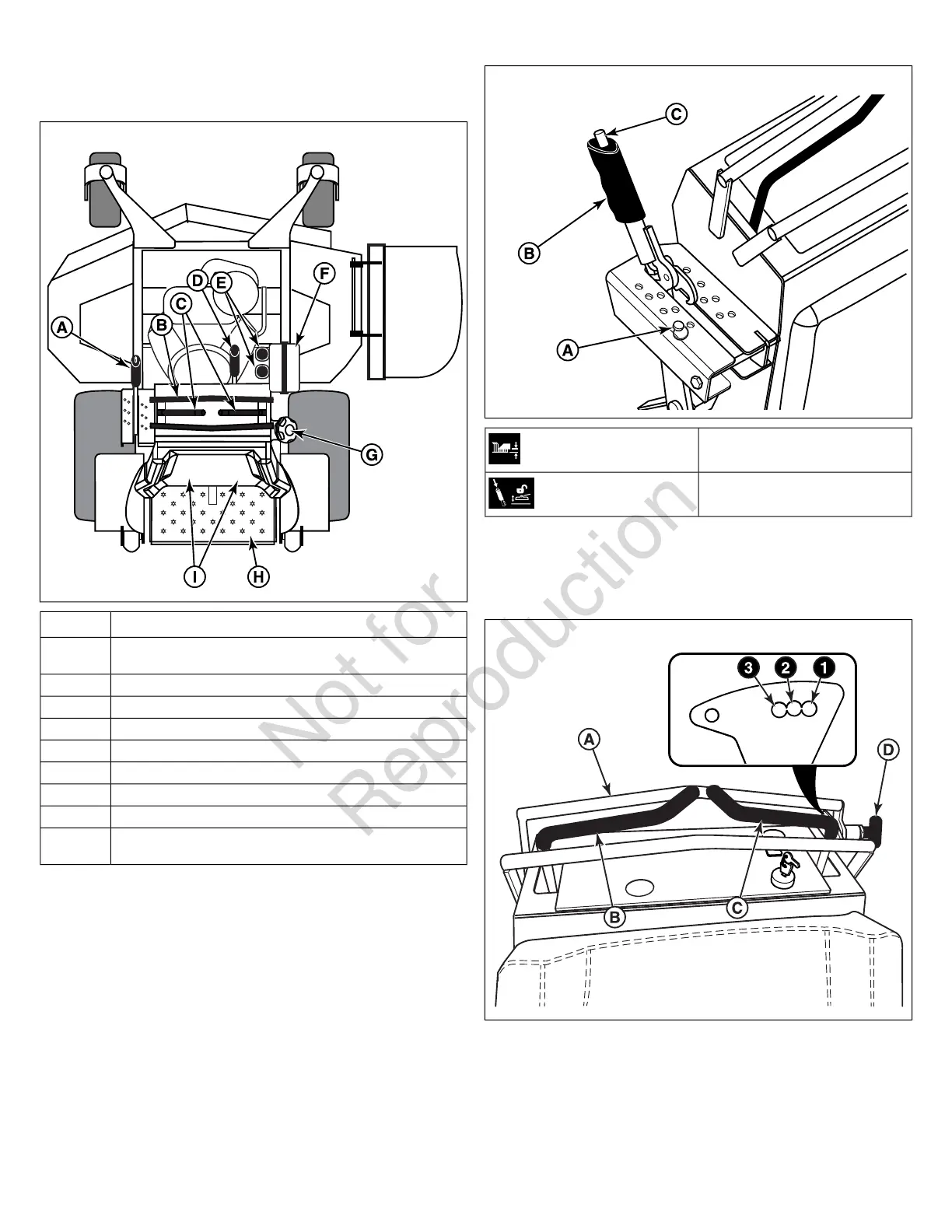
DescriptionCallout
Deck Lift Lever, Cutting Height Adjustment Pin, and Deck Lift
Release Button
A
Maximum Forward Speed BarB
Ground Speed Control LeversC
Parking BrakeD
Transmission Oil Fill (Transmission Oil Reservoirs)E
Battery BoxF
Fuel Tank CapG
Operator PlatformH
Transaxle Release Levers (Located behind Operator Support
Cushion)
I
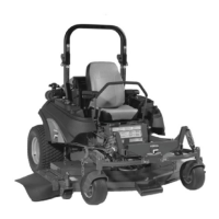
Deck Lift Lever, Cutting Height Adjustment Pin, and Deck
Lift Release Button: The deck lift lever (B, Figure 5), cutting
height adjustment pin (A) and deck lift release button (C), are
used together to control the cutting height of the mower deck.
See
Cutting Height Adjustment
for instructions on using these
controls.
5
Cutting Height Adjustment Pin
Deck Lift Lock Lever
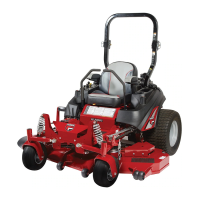
Maximum Forward Speed Bar: This unit is equipped with an
adjustable Maximum Forward Speed Bar (A, Figure 6), which
is located in front of the Ground Speed Control Levers (B & C).
6
The Maximum Forward Speed Bar can be adjusted in three
different positions to suit the desired maximum forward speed
of the operator. The positioning hole closest to the ground speed
control levers (labeled as #1 in Figure 6) is the lowest setting
and the positioning hole furthest from the ground speed control
levers (labeled as #3) is the fastest.
12 ferrismowers.com