Ferroli F24
6
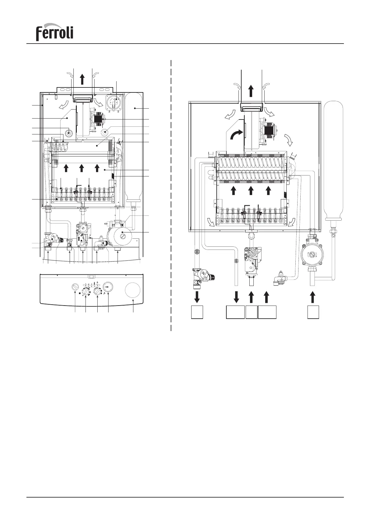
2.03 Boiler water fl ow diagram
OUT
IN
MIN
AIR
IN
AIR
IN
FLUE
OUT
C.H.
OUT
D.H.W.
OUT
GAS
IN
D.H.W.
IN
C.H.
IN
Fig. 3
2.02 Boiler main components
Key
5 Room sealed compartment
7 Gas inlet
8 Domestic hot water outlet
9 Domestic hot water inlet
10 Central heating flow outlet
11 Central heating return inlet
14 Safety valve
16 Fan
19 Combustion chamber
20 Burner assembly
21 Main injector
22 Burner
26 Combustion chamber insulation
27 Copper heat exchanger for central heating and
domestic hot water
28 Flue collector from heat exchanger
32 Central heating pump
34 Central heating flow temperature sensor
36 Automatic air vent valve
42 Domestic hot water flow
temperature sensor
Fig. 2
43
16
27
50
19
49
28
5
20
21
26
132
90
91
818222
56
IN
OUT
MIN
RESET
OFF
ON
0
5
1
2
3
4
6
bar
98 63 157 145
°C
°C
62
10 8 784 85 44
136
32
36
114
34
14 42 9 11
43 Air pressure switch
44 Gas valve
49 Safety overheat thermostat
50 Central heating flow limit thermostat
56 Expansion vessel
62 Time clock
63 Central heating temperature adjustment
81 Ignition electrode
82 Sensor electrode
84 Primary gas valve solenoid
85 Secondary gas valve solenoid
90* Flue sampling point
91* Air sampling point
98 On/Off/Reset switch
114 Low water pressure cut off switch
132 Flue gas deflector
136 Flow meter
145 Central heating pressure gauge
157 Domestic hot water temperature adjustment
* For use with flue gas analysis equipment