Do you have a question about the Ferroli DIVAcondens F24 and is the answer not in the manual?
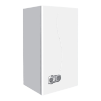
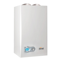
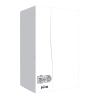
Introduces the DIVAcondens F24/F28 as a high-efficiency condensing heat generator.
Explains the display indications for heating, DHW, comfort, and fault conditions.
Details how to connect the power supply and switch the boiler on/off.
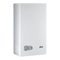
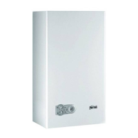
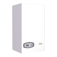
Identifies and explains the components of the boiler's control panel and their functions.
Instructions on how to adjust the domestic hot water (DHW) temperature.
How to set room temperature using an optional thermostat.
How to set room temperature using an optional remote timer control.
Explains the ECO and COMFORT modes for DHW delivery speed and comfort.
Details adjustments managed via a connected Remote Timer Control.
How to check and adjust the system water pressure using the filling cock.
Emphasizes that installation must be performed by qualified personnel according to regulations.
Specifies requirements for the boiler's installation location, including ventilation and protection.
Provides guidance on plumbing connections, including safety valve outlet and water system characteristics.
Details the requirements for making a safe and compliant gas connection.
Outlines the procedures for electrical connections, including earthing and polarity.
Instructions on fitting baffles supplied with the unit for fume outlet pipe installation.
Table detailing baffles used for separate duct installations based on loss calculations.
Details various adjustments like gas conversion, test mode, and pressure settings.
Covers pre-startup checks and essential operational checks after lighting the boiler.
Explains the self-diagnosis system and how fault codes are displayed.
Lists potential faults, their causes, and recommended cures for troubleshooting.
Key to component numbering used in various diagrams of the boiler.
Provides dimensional drawings and connection points for the boiler unit.
Diagram illustrating the hydraulic circuit for the heating system.
Diagram illustrating the hydraulic circuit for the domestic hot water (DHW) system.
Graphs showing pressure and flow characteristics for different operating conditions.
Graph illustrating the relationship between pump speed and head/pressure losses.
Product fiche details for the DIVACONDENS F24 model, including energy efficiency and consumption data.
Product fiche details for the DIVACONDENS F28 model, including energy efficiency and consumption data.
| Type | Condensing |
|---|---|
| Fuel Type | Natural Gas / LPG |
| Maximum Heating Output | 24 kW |
| Mounting | Wall-mounted |
| Central Heating Output | 24 kW |
| DHW Output | 24 kW |
| NOx class | 6 |
| Water pressure | 0.5 - 3 bar |
| Flue Type | Room-sealed |
| Hot Water Production | Yes |