Do you have a question about the Ferroli RPA 38-50 and is the answer not in the manual?
General guidelines for manual usage, installation, and compliance.
Compliance with European safety standards and directives.
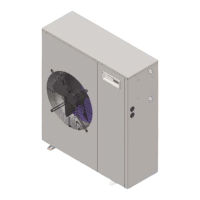
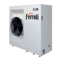
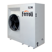
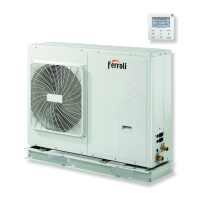
Overview of the unit's main components and their functions.
Details on components within the hydraulic and chilling circuits.
Details on the electrical panel, monitoring system, and control components.
Technical data for the cold-only series of units.
Technical data for the heat pump series using R22 refrigerant.
Technical data for the heat pump series using R407C refrigerant.
Information on how the appliance is supplied and what is included.
Procedures for checking the appliance upon delivery for completeness and damage.
Strict adherence to regulations for preventing injuries and machine damage.
Instructions for safely moving and positioning the appliance.
Guidelines for selecting an appropriate location for the unit.
Steps for connecting a drain for condensation produced in heating mode.
Detailed measurements and diagrams of the unit sizes.
Overview of electrical components within the unit.
General guidelines and specifications for making electrical connections.
Wiring diagram specific to models 16 and 19.
Wiring diagram specific to models 24, 30/2, and 38/2.
Wiring diagram specific to models 30/3, 38/3, 42/3, and 50/3.
Explanation of the components and connections shown in the wiring diagrams.
Local laws and suggestions for designing the hydraulic circuit.
Guidance on pipe bending, support, and leak prevention.
Diagram and notes for hydraulic connections without an accumulation kit.
Diagram and notes for hydraulic connections with an accumulation kit.
Methods for preventing freezing by emptying or using glycol.
Instructions for installing quick couplings for system connections.
Graph and table illustrating load loss values based on flow rate and temperature.
Table detailing operating limits for different unit sizes and modes.
Explanation of water flow and pump speeds with accumulation kit.
Graphs showing primary circuit pump performance for different accumulators.
Graphs showing secondary circuit pump performance for different accumulators.
Guidance on system water volume and expansion tank requirements.
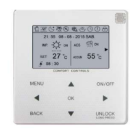
Description of the controller, display, and buttons.
Explanation of the status LEDs (Compressor, Antifreeze, Defrosting).
How to display temperature readings from various probes.
How to select cooling, heating, or standby modes using the controller.
List of alarm codes, their meanings, and how to reset alarms.
Overview of the controller's menu hierarchy and parameters.
Requirements for validating warranty and initial setup.
Importance of maintenance and safety precautions.
Recommended checks and frequencies for regular maintenance.
Reducing risks to persons and the environment.
Information on refrigerants (R22, R407C) and their handling.