5 Mounting and installation instructions
Warning
Electric shock
Injury to people, damage to the machine and system.
Switch off the power supply before mounting or removing the module (risk of
malfunctions or damage).
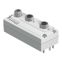
The module is mounted in an interlinking block of the CPX terminal.
1
2
3
4
1 Module
2 Interlinking block
3 Contact rails
4 Screws, tightening
torque:0.9...1.1 Nm
Fig. 4
5.1 Dismantling
Unscrew the screws and carefully remove the module.
Note
Material damage due to incorrect mounting
Select screws that are suitable for the material of the interlinking block:
– plastic: Thread-cutting tapping screws
– metal: Screws with metric thread.
When ordering a single module without a CPX terminal, both types of screws are
supplied.
5.2 Mounting
1. Check the seal and sealing surfaces.
2. Push the module carefully and without tilting as far as possible into the inter
linking block.
3. Insert the screws so that the existing threads are used.
4. Tighten the screws by hand in diagonally opposite sequence. Tightening torque:
0.9…1.1 Nm.
5.3 Electrical installation
Terminal specifications:
– conductor cross section: 0.13 … 1.5 mm
2
– stripped insulation: 5 … 6 mm.
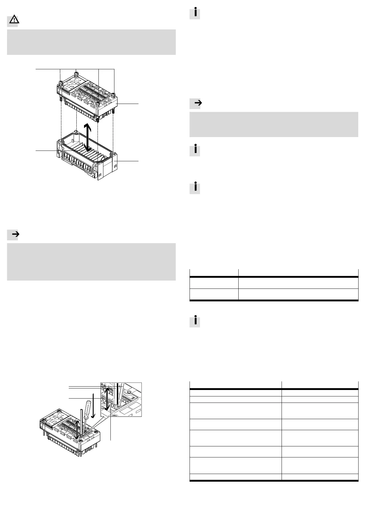
1. To unlock the terminal depress the release mechanism with a screwdriver.
2. Insert or remove the conductor.
3. Remove the screwdriver from the release mechanism.
1
2
3
4
1 Screwdriver,
blade 2.5 × 0.4 mm
2 Conductor
3 Terminal release (inside)
4 Terminal opening for inserting the
conductors (outside)
5 Terminal
Fig. 5
To comply with protection class IP65/IP67, use the cover AK-8KL and the
VG-K-M9 fittings kit. Observe the relevant assembly instructions when
doing this.
6 Commissioning and configuration
6.1 Commissioning
1. Check the module and peripheral equipment.
2. Check the CPX terminal and its power supply.
3. Commission the entire system (è CPX system description, è description of the
bus node used, è description of the module).
6.2 Configuration
The Festo Maintenance Tool for CPX terminals (CPX-FMT) or the higher-order con
troller can be used for the configuration process.
Note
Malfunction due to faulty configuration
When using the higher-order controller for the configuration process, the config
uration options are not restricted to the operating mode-specific settings.
Only perform configuration settings that are described in the module description.
The configuration settings created in the CPX-FMT can be exported as a
configuration file for many common control systems (è CPX-FMT online
help).
6.3 Parameterisation
For information regarding parameterisation, module replacement and start
behaviour, please refer to the module description.
6.4 Operating modes
The module provides operating modes for:
– counting
– measuring
– position and speed determination
– pulse output
– motor operation.
7 Diagnostics
The following possibilities for diagnostics and error handling are available, de
pending on the parameterisation of the module:
Diagnostics option Description
LED display The LEDs directly display hardware faults, configuration errors, bus
errors, etc.
CPX diagnostic function The module reports specific malfunctions as error messages (error
numbers) to the CPX bus node or CPX-FEC/CPX-CEC.
Fig. 6
For details regarding diagnostics, please refer to the module description.
8 Maintenance, repair, disposal
The module does not contain any wearing parts.
Replace the module if it becomes defective.
If possible, send the defective module together with a description of the error
and application to Festo for analysis.
Dispose of electronic components using a certified waste disposal company.
9 Technical data
Type CPX-2ZE2DA
General technical data è description P.BE-CPX-2ZE2DA-…
Protection class in accordance with EN 60529 IP65/IP67
Protection against electric shock, protection against
direct and indirect contact in accordance with
IEC 60204-1
by means of PELV circuits
(Protected Extra-Low Voltage)
Operating voltage supply
– electronics/sensors (U
EL/SEN
) 18 … 30 V DC
Intrinsic current consumption at 24 V
– from operating voltage supply for electronics/
sensors (U
EL/SEN
)
max. 370 mA
Continuous output current
– continuous output current of the digital output DO max. 5 A (parameterisable)
Continuous nominal current
– encoder/sensor supply 24 V DC
– encoder supply 5 V DC
max. 1 A
max. 1 A
Parallel connection of outputs to increase power is not permissible
Fig. 7
 Loading...