CPX-2ZE2DA
input/output module
Festo AG & Co. KG
Ruiter Straße 82
73734 Esslingen
Germany
+49 711 347-0
www.festo.com
Brief description
Translation of the original instructions
8101596
2018-11a
[8101598]
CPX-2ZE2DA input/output module English................................
For all available product documentation è www.festo.com/pk
1 Intended use
When used in combination with a CPX terminal, the CPX-2ZE2DA input/output
module enables
– the processing, analysis and generation of pulses and measured values
– the output of signals and voltages.
The module is intended for use in an industrial environment. Outside of industrial
environments, e.g. in commercial and mixed-residential areas, actions to suppress
interference may have to be taken.
The module is exclusively intended for use in CPX terminals from Festo and for
installation in machines or automated systems, and it may only be used as follows:
– in perfect technical condition
– in original status without unauthorised modifications, except for the adapta
tions described in this documentation
– within the limits of the product defined by the technical data (è Chap. 9).
2 Safety
This documentation is directed exclusively at technicians trained in control and
automation technology.
Detailed information can be found in the module description
(è P.BE-CPX-2ZE2DA-...) as well as in the CPX system description
(è P.BE-CPX-SYS-...).
Warning
Electric shock
Injury to people, damage to the machine and system.
For the electrical power supply, use only PELV circuits in accordance with
IEC 60204-1 (Protective Extra-Low Voltage, PELV).
Observe the general requirements of IEC 60204-1 for PELV circuits.
Use only voltage sources which guarantee reliable electrical isolation of the
operating and load voltage in accordance with IEC 60204-1.
Always connect all circuits for operating and load voltage supplies U
EL/SEN
,
U
VAL
and U
OUT
.
Note
Electrostatic charge
Damage to the internal electronics.
Ensure assembly personnel are electrostatically discharged before
conducting any assembly work.
Note
Take into consideration the specifications and instructions in the module de
scription and the assembly instructions for the components.
Commission the module only if fully mounted and wired.
3 Transport and storage conditions
Protect the product during transport and storage from the following
– mechanical loads
– impermissible temperatures
– moisture
– aggressive atmospheres.
Only store and transport the product in its original packaging.
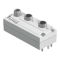
4 Connection and display components
1
2
3
4
5
6
7
8
aA
aB
9
aJ
aC
aD
aE
Status - inputs for channel 0
1 Encoder input 1 (green)
2 Encoder input 2 (green)
3 Encoder input 3 (green)
4 Digital input DI (green)
Status - inputs for channel 1
5 Encoder input 1 (green)
6 Encoder input 2 (green)
7 Encoder input 3 (green)
8 Digital input DI (green)
Status - outputs
9 Digital output DO channel 0 (yellow)
aJ Digital output DO channel 1 (yellow)
Diagnostics
aA Module error (red)
aB Digital output DO channel 0 (red)
aC Digital output DO channel 1 (red)
aD Encoder supply 24 V (red)
aE Encoder supply 5 V (red)
Fig. 1
The assignment illustrated here may vary in individual operating modes.
For details regarding the operating modes, please refer to the module
description.
Fig. 2
Channel 0 Channel 1
Terminal Allocation Terminal Allocation
X1 .0 Encoder input 1 + X5 .0 Encoder input 1 +
.1 – .1 –
.2 Encoder input 2 + .2 Encoder input 2 +
.3 – .3 –
X2 .0 Encoder input 3 + X6 .0 Encoder input 3 +
.1 – .1 –
.2 Encoder supply 5 V
1)
+ .2 Encoder supply 5 V
1)
+
.3 – .3 –
X3 .0 Encoder supply 24 V
1)
+ X7 .0 Encoder supply 24 V
1)
+
.1 – .1 –
.2 Encoder supply 24 V
for DI
1)
+ .2 Encoder supply 24 V
for DI
1)
+
.3 Digital input DI .3 Digital input DI
X4 .0 Reference potential for
encoder supply 24 V
for DI
– X8 .0 Reference potential for
encoder supply 24 V
for DI
–
.1 Digital output DO .1 Digital output DO
.2 Reference potential for DO .2 Reference potential for DO
.3 Functional earth (FE) .3 Functional earth (FE)
1) Protected against short circuit and overload
Fig. 3