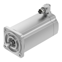
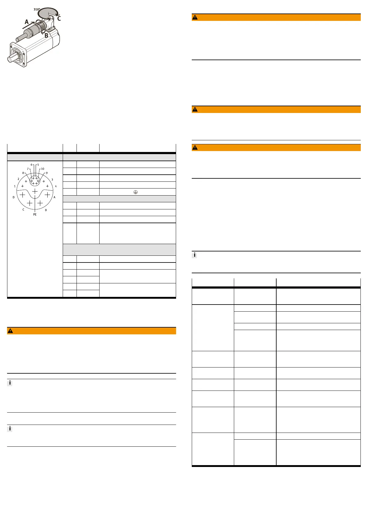
Fig. 2 Connect and align motor cable
Connect cable
Requirement
– Select accessories èwww.festo.com/catalogue.
– Observe permissible cable length and conductor cross section
èwww.festo.com/catalogue.
– Use screened cables.
1. Connect the cable (A) to the plug and tighten the screw-type lock (B).
2. Align plug (C) (can be swivelled 310°).
3. Connect the cable to the servo drive.
Instructions for servo drive and cable èwww.festo.com/sp.
Plug, M23, 15-pin, pins Pin Function Description
Servo motor EMMT-AS-...
A U Motor phase U
B V Motor phase V
C W Motor phase W
D – not connected
PE PE Protective earthing
Holding brake EMMT-AS-...-...B
1 BR– Reference potential 0V
2 – not connected
3 – not connected
4 BR+ Holding brake control:
– 24VDC (21.6…25.44VDC): open
(vented)
– 0VDC: closed (retracted)
EnDat 2.2 absolute encoder, single-turn/multi-turn EMMT-
AS-...-...S/M
5 U
S
Supply voltage 3.6...14VDC
6 GND Ground 0V
7 DATA
8 #DATA
Data cable, bidirectional, RS485-compliant,
differential
9 CLOCK
10 #CLOCK
Clock line, input, RS485-compliant, differen-
tial
Tab. 3 Plug for motor, holding brake and absolute encoder
9 Commissioning
9.1 Safety
WARNING!
Risk of injury due to unexpected movement of components.
• When releasing the holding brake, secure the driven mechanical system to
prevent unintended movement.
• Deenergise the motor before releasing the holding brake manually.
• Before setting the enable signal, protect the traversing range of the driven
mechanical system from access.
High voltage loss in the motor cable can result in the permissible operating
voltage of the holding brake being undershot.
• Observe permissible cable length and conductor cross section
èwww.festo.com/catalogue.
9.2 Performing commissioning
Commissioning of the drive system may only be carried out with the confirmation
of conformity in accordance with EN 61800.
1. Commission the motor in combination with a suitable servo drive.
Instructions for servo drive èwww.festo.com/sp.
2. Check function and holding torque of the holding brake.
For the grinding-in process of the brake system, briefly close the holding
brake at low speed, e.g.3s at 100rpm.
10 Operation
WARNING!
Danger of burns from hot housing surfaces.
Metallic housing parts can reach high temperatures during operation.
Contact with metal housing parts can cause burn injuries.
• Do not touch metallic housing parts.
• After the power supply is switched off, let the device cool down to room tem-
perature.
• Check the function and holding torque of the holding brake at regular inter-
vals.
If the holding torque is reduced, close the holding brake briefly at low speed,
e.g.3s at 100rpm.
11 Maintenance
11.1 Disassembly
WARNING!
Risk of injury due to electric shock.
• Switch off power supply prior to assembly and installation work; ensure that
it is off and secure it against being switched back on.
Cancelling the enable signal is not sufficient.
WARNING!
Risk of injury due to unexpected movement of components.
• Bring moving parts of the connected mechanical system into a secure posi-
tion (e.g. for vertical installation, move the slide into the lower end position).
• Only then should you disconnect the motor from the mechanical system.
11.2 Replace the rotary shaft seal
For variants with rotary shaft seal EMMT-AS-...-...R-...:
• Rotary shaft seal EASS must be replaced after 5,000 operating hours at the
latest èInstructions for rotary shaft seal, www.festo.com/sp.
11.3 Cleaning
Before cleaning, the product must be cooled down to below 40°C.
Clean the outside of the product with a soft cloth as required. Cleaning agents
include all non-abrasive media.
12 Malfunctions
12.1 Fault clearance
Repairs may only be carried out by the Festo repair service.
• Motor must not be opened.
Malfunction Possible cause Remedy
Loud rotation noises of
the motor shaft.
Coupling distance too
short.
Observe permissible coupling spacings
èInstruction manual for motor mounting kit,
www.festo.com/sp.
Excessive load. Reduce load.
Servo drive has not yet
been enabled.
Check signals.
Holding brake closed. Release holding brake.
Motor shaft does not
turn.
Min. operating voltage
for opening the holding
brake is not reached.
– Comply with permissible cable length and
cable cross section
èwww.festo.com/catalogue.
– Contact local Festo Service.
Torque of the motor
shaft is not transmitted
to the drive system.
Coupling slips. Check the mounting of the shaft-hub connection
èInstruction manual for the motor mounting
kit, www.festo.com/sp.
Motor shaft vibrates. Current controller set-
tings.
Optimise controller data, e.g.velocity, accelera-
tion, ...
Motor shaft rotates in
the wrong direction.
Cabling error. Check and correct cabling.
Holding torque of the
holding brake is not
reached.
Insufficient condition-
ing of the brake disc.
Briefly close the holding brake several times at
low speed, e.g.3s at 100rpm.
Holding torque of the
holding brake not
effective.
Holding brake fault,
e.g.excessive axial
force on the motor
shaft.
– Replace motor
èwww.festo.com/catalogue.
– Observe max. permissible axial force,
e.g.mount the coupling so it is free of ten-
sion.
Cabling error. Check and correct cabling.Encoder signals not
transmitted.
Encoder fault,
e.g.excessive axial
force on the motor
shaft.
– Replace motor
èwww.festo.com/catalogue.
– Observe max. permissible axial force,
e.g.mount the coupling so it is free of ten-
sion.
Tab. 4 Overview of fault clearance
12.2 Repair
Send the product to the Festo repair service for repair.
 Loading...