Radar Training System, LabVolt Series
© Festo Didactic 36
Direct CW Doppler and FM-CW outputs are provided. Quadrature detection (I- and Q-channel outputs) is used
for the pulse radar. Wideband amplifiers are used in the I- and Q-channels to ensure faithful baseband
reproduction of the received RF signals.
Unregulated DC power is automatically supplied to the Radar Receiver through self-aligning connectors when it
is installed on the Power Supply / Antenna Motor Driver.
Specifications
Parameter Value
Type Direct Conversion - DC-IF
Detector Type Quadrature
RF Input Frequency Range 8 to 12.4 GHz
Bandwidth 600 MHz
Sensitivity Noise Figure better than 18 dB
Local Oscillator Input Power +11 dBm (+13 dBm maximum)
I- and Q-Channel Pulsed Output Voltage Range -700 to +700 mV
CW Doppler Output Voltage Range -15 to +15 V
FM-CW Output Voltage Range -15 to +15 V
Faults 6, switch-insertable
Test Points 10
Physical Characteristics
Dimensions (H x W x D) 162 x 330 x 300 mm (6.4 x 13 x 11.8 in)
Net Weight 4.8 kg (10.6 lb)
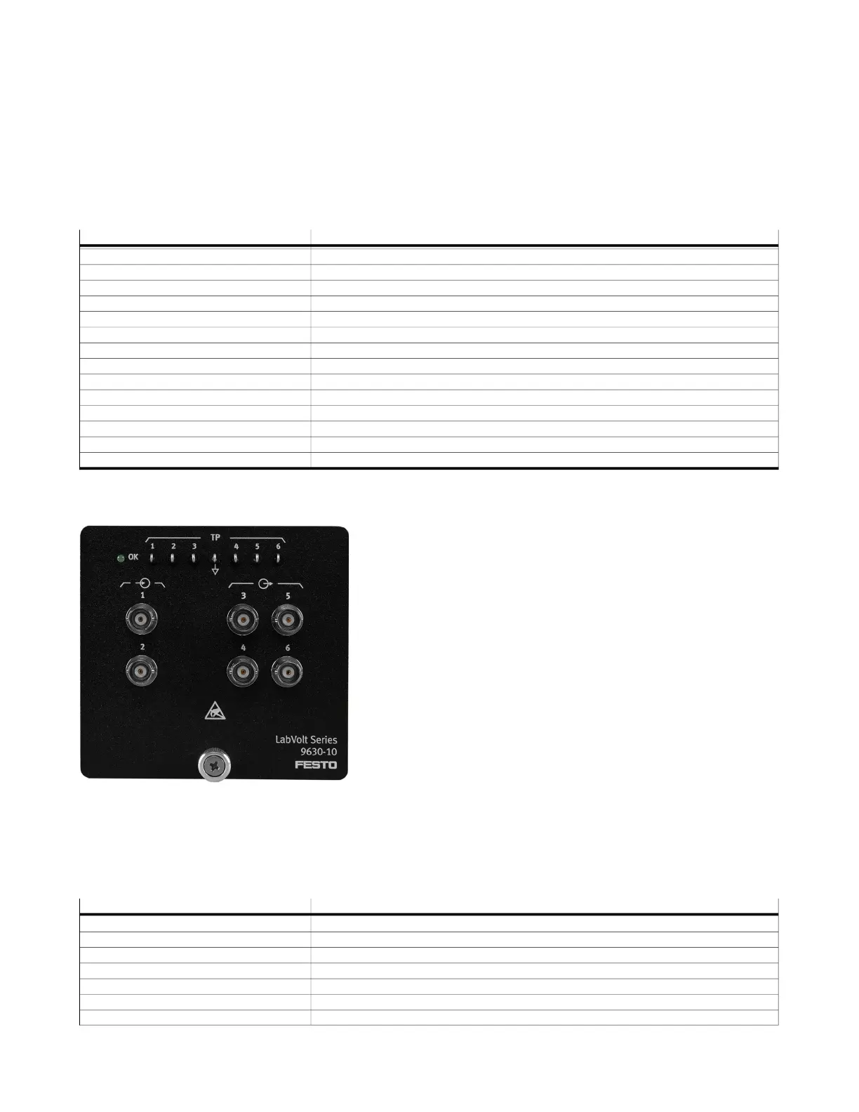
Analog/Digital Signal Combiner
8112776 (9630-10)
The Analog/Digital Signal Combiner is a compact module
designed to be installed into one of the slots on the RTM of the
Radar Processor/Display. This module converts the clutter and
interference generated by the DSP of the RTM to analog format,
and adds it to the I- and Q-channel echo signals coming from the
Radar Receiver.
The Analog/Digital Signal Combiner has two BNC-connector
inputs to receive the I- and Q-channel echo signals. It also has
four BNC-connector outputs. Two outputs provide the clutter and
interference signals added to the I- and Q-channel echo signals.
The other two outputs provide the I- and Q-channel, perturbed
echo signals. All these inputs and outputs are protected from
misconnections within the system. Test points are available on
the module's front panel to observe all these signals using a
conventional oscilloscope.
DC power is automatically supplied to the Analog/Digital Signal Combiner when it is installed into the RTM.
Specifications
Parameter Value
Analog Inputs (2)
Voltage Range -10 to +10 V
Impedance 10 kΩ
Analog Outputs 3 and 4
Voltage Range -1 to +1 V
Impedance 600 Ω
Analog Outputs 5 and 6
 Loading...