9
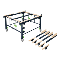
Push extension table onto roughly the
same level as the saw table and fasten with
left and right rotary knobs (3.8). The brass
collar on the rotary knobs should rest in
the base of the slot.
Align the table lengthener on the direct join
with the table base to a position slightly be-
low the surface of the table base (check by
placing the stop ruler on the table base).
Fasten fi tting angle with bolts (3.10).
Check that the entire surface of the exten-
sion is fl at with the stop guide.
Adjust at the fastenings (3.5).
Folding away the extension table:
Release rotary knobs (3.8).
Loosen knurled nuts (3.3).
Slightly raise the rear of the extension table
and remove ends of supports from slots.
Fold supports in crosswise.
Fold down extension table.
3 Ripping-cut fence CS 70 LA (1.3)
Precise sawing work with large work pieces is
only possible with a correctly fi tted ripping-
cut fence CS 670 LA (Fig. 4).
The ripping-cut fence has separate clamps
for the front and rear edges of the table.
This prevents a lateral movement of the
stop surface.
The stop guide (4.7) can be fi tted to the stop
rail (4.5) as a high or low guide surface.
Rotate the stop guide by 90° and fasten to
the corresponding guide grooves.
The following adjustments are possible
with the ripping-cut fence:
Handle (4.2): Clamp stop to front edge of
table
Claming lever (4.3): Clamp stop to rear
edge of table.
Clamping lever (4.1): Clamp fi ne adjust-
ment.
Rotary knob (4.10): Stop adjustment with
fi ne adjustment
Rotary knobs (4.6): Clamp stop guide to
stop rail.
Open the following clamps fully in prep-
aration for fi tting the fence:
Clamp on front edge of table (4.2)
Clamp on rear edge of table (4.3). (clamp-
ing lever in a vertical upright position)
Clamp on fi ne adjustment (4.21). (clamp-
ing lever points towards switch)
Then slid the fence over the table from the
right so that the clamp jaws of the front
and rear clamps lie below the peripheral
table clamping edge (4.4).
The adjustment range for the fi ne adjust-
ment an be seen in the inspection window
(4.9). Set a suffi ciently large adjustment
range for subsequent adjustments with the
rotary knob (4.10).
Then slide the fence according to scale
close to the desired cutting width and
clamp by fl ipping the clamping lever (4.1)
approx. 180° to the fi ne adjustment.
If the clamp is too weak the clamping
lever can be moved as follows:
Bring clamping lever into maximum clamp-
ing position.
Release bolt which holds the clamping lever
to the axis.
Set clamping lever back by one division on
the hexagon.
Re-tighten clamping lever.
Set fence to exact size with fi ne adjust-
ment using rotary knob (4.10). The fence
is hereby moved by 1/10 mm for every
scale mark.
Tighten fence clamps (4.2 + 4.3) after fi nal
adjustment.
 Loading...