8
Compact CS70 Accessories
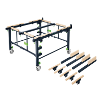
1 Extension table CS 70 VB
2 Extension table CS 70 VL
3 Ripping-cut fence CS 70 LA
1 Extension table CS 70 VB (1.1)
The extension table CS 70 VB can be fi tted
to the base table to enable exact cuts with
a stop up to a cutting width of 680 mm.
The saw table is widened by 405 mm if an
extension table is fi tted on a long side of the
table (usually the right).
Proceed as follows (Fig. 2):
Unfold supports (2.5) at a 90° angle to the
table top.
Turn rotary knobs (2.8) fully to the left.
Place the outer edge of the extension table
on the edge of the base table in a slightly
raised position (Fig. 2).
Lower extension table so that the periph-
eral clamping edge (2.4) lies between
the profi le edge (2.7) and clamping plate
(2.7).
Insert the end of the front support (2.2)
into the slot (2.1) in the table frame, push
down and tighten with knurled nut (2.3).
Suspend rear support in slot. Push exten-
sion table down and tighten rear knurled
nut.
Adjust exact height. Place guide stop on
base table up to saw blade.
Adjust height of extension table to same
height as base table with screwdriver at
the adjusting screws (4.8).
Attention! Do not align with outer edge of
table since this may be 0.2-0.3 mm below
the rest of the table.
Fit angle fence (1.4) centrally over joint
between base table and extension table so
that when the fence is clamped the exten-
sion table is aligned with the edge of the
base table.
Tighten front rotary knob (2.8).
Push extension table down on joint at rear
and tighten rear rotary knob.
Then remove the angle fence.
Screw in adjusting screw (2.10) fully with
screw-driver. If the extension table is re-
moved and then re-mounted it must be
pushed back against this stop (adjusting
screw).
This fi xation means that it no longer has
to be aligned with the angle fence.
Check that the extension table is exactly
level with the base table using the guide
stop.
The fl atness of the base table can be ad-
justed by adjusting the fastening (2.6).
To enable the angle fence and ripping-cut
fence to be adjusted according to the exist-
ing scale, the scale of the extension table
must be fi tted directly onto the base table’s
scale (Fig. 4).
Proceed as follows:
Release the fastening bolts (4.11) for the
extension table’s scale.
Slide the scale to the correct setting.
Re-tighten fastening bolts.
2 Extension table CS 70 VL (1.2)
The extension table CS 70 VL can be mount-
ed on the rear of the CS 70 EB to provide
a safe support when sawing longer work
pieces.
The saw table is thus extended by 530
mm.
Proceed as follows (Fig. 3):
Mount left and right fi tting angle (3.6) to
rear of frame with enclosed bolts, square
nuts and washers. Tighten the bolts
(3.10).
If a CS 70 ST sliding table is already fi tted
the fi tting angle for the extension table is
placed on the fi tting angle for the sliding
table on the side of the sliding table and
both fi tting angles fastened together (on
top of one another).
The enclosed 4 mm washer then has to be
inserted beneath the fi tting angle on the
other side.
Unfold supports (3.4) at a 90° angle to the
tabletop.
Release left and right rotary knobs (3.8)
by approx. 3-4 rotations (turn anti-clock-
wise).
Suspend the extension table by the thread-
ed bolts of the rotary knobs (3.8) in the
slots (3.9) on the fi tting angle in a slightly
raised position.
The fi tting angle hereby lies between the
rotary knob (3.8) and bow (3.7).
Lower the extension table onto roughly the
same level as the saw table and insert the
end of the support (3.2) into the slot (3.1)
in the table frame, press down and fasten
with knurled nut (3.3).
 Loading...