CLIP LIMITER
A clip limiter will engage if excessive clipped signal occurs. A degree of clip is allowed before the
limiter is engaged. The limiter will disengage when the clipped signal returns to an un-clipped
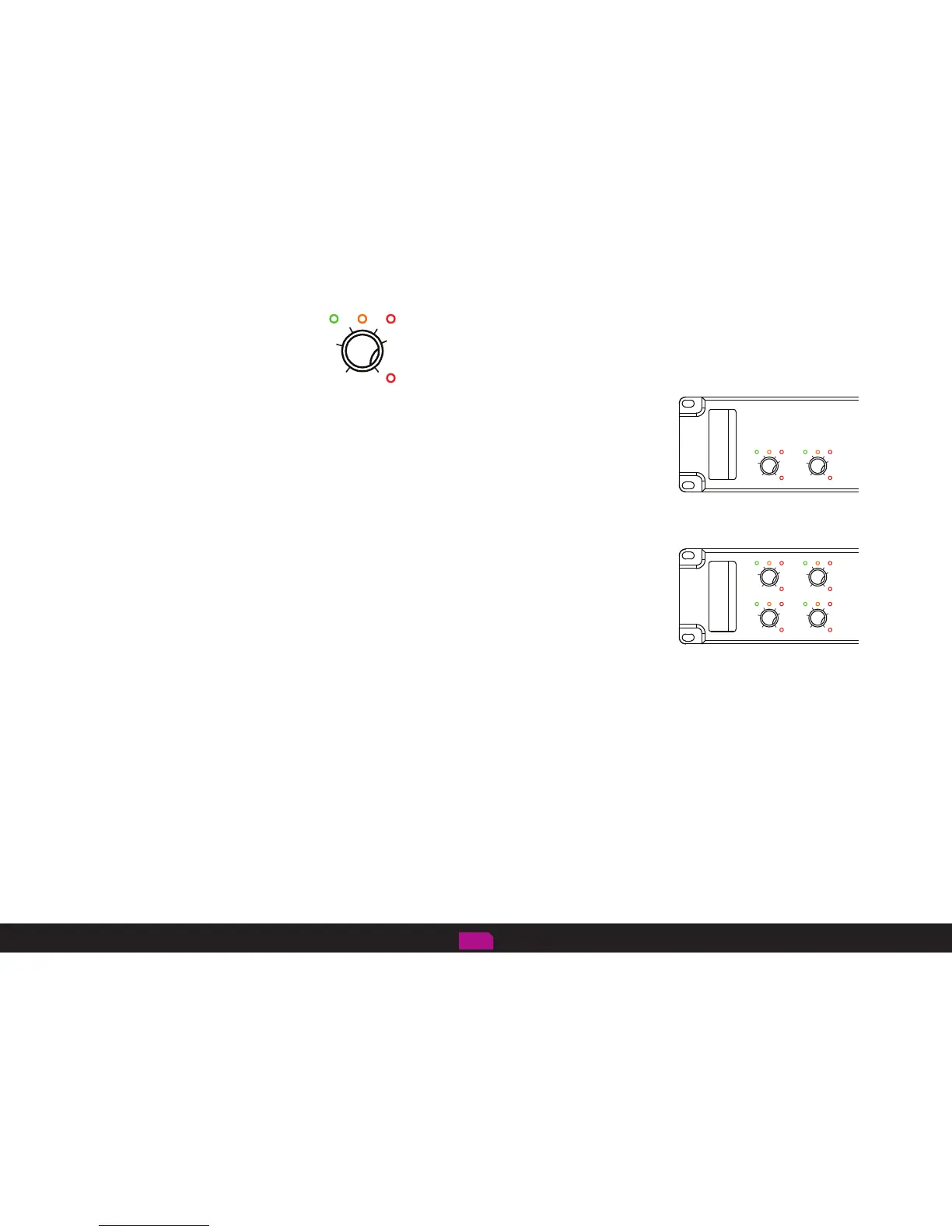
state. The clip limiter is indicated by the ‘clip’ red LED flashing in line with the audio signal.
DC PROTECT
If DC occurs due to an amplifier fault or inappropriate audio input signal the amplifier DC protection
circuit will engage and the amplifier will turn off. The circuit will reset when the amplifier is turned
back on. The amplifier will continue to turn off if a genuine DC fault condition is present.
The amplifier should be returned for service if this occurs.
AMPLIFIER PROTECTION
The amplifier will mute in event of a load short circuit or current overload.
THERMAL CONSIDERATIONS WHEN USING YOUR FFA AMPLIFIER
IMPORTANT! REAR AIR INLETS AND FRONT HOT AIR EXHAUSTS MUST NOT BE OBSTRUCTED. THIS COULD CAUSE THE AMPLIFIER TO MUTE
ITS AUDIO OUTPUTS PREMATURELY.
Individual amplifier channels will mute if the thermal threshold is exceeded. Amplifier channels will un-mute when sufficient cooling has taken
place. If the FFA amplifiers are to be fitted within a sealed type rack enclosure with input fans fitted to the rack lids, these fans must be capable
of at least 120 CFM per amplifier fitted within the rack.
Care should be taken when mixing amplifier brands within the same rack enclosure with respect to cooling airflow orientation. Ideally airflow
should all go in the same direction. – Air intake: FFA amplifiers intake cool air from the rear of the amplifier and the hot air exhaust is through
the front panel of the amplifier.
FFA air flow convention is used as we believe this is the best way to remove hot air away from the amplifier and the rack it is installed within. The
rear of the amplifier rack can be crowded with cables and possibly patch panels which can impede the hot air as it is expelled from the amplifier.
Load protection
-20
-20
C D
A B
-6
-2
-12
-6
-20
-2
Protect
-12
Ch
-2
-12
-6
-20
-2
-3dB
-12
Sig
-6
Clip
Sig Clip-3dB
Protect
Ch
Sig Clip-3dB
Protect
Ch
Sig Clip-3dB
Protect
Ch
-20
A B
-6
-2
-12
-6
-20
-2
-12
Sig Clip-3dB
Protect
Ch
Sig Clip-3dB
Protect
Ch
2 channel
4 channel
-20
-2
-12
-6
Sig Clip-3dB
Protect
pg 12