3
3. Mechanical Installation
3.1 Introduction
The following tools will be needed:
• 3mm hexagon key for lid screws
• 4mm hexagon key to adjust SET LEVEL
• Wire strippers and wire cutters
• 3mm flat blade torque screwdriver for terminal block electrical connections
• 5mm flat blade torque screwdriver for internal protective earth terminal
• Adjustable spanner to fit cable gland
• Installation of the vibration switch shall only be carried out by qualified personnel
• Remove vibration switch from carton
• Vibration switch is factory set to 3 g, unless a preset switch has been ordered
• To reduce the risk of damaging internal components and wiring, installation and wiring must
be performed within a temperature range of -10°C to +50°C
• Do not allow moisture or other airborne contaminants inside the switch as they can cause
corrosion
• When closing the lid, ensure the seal is not lost or damaged.
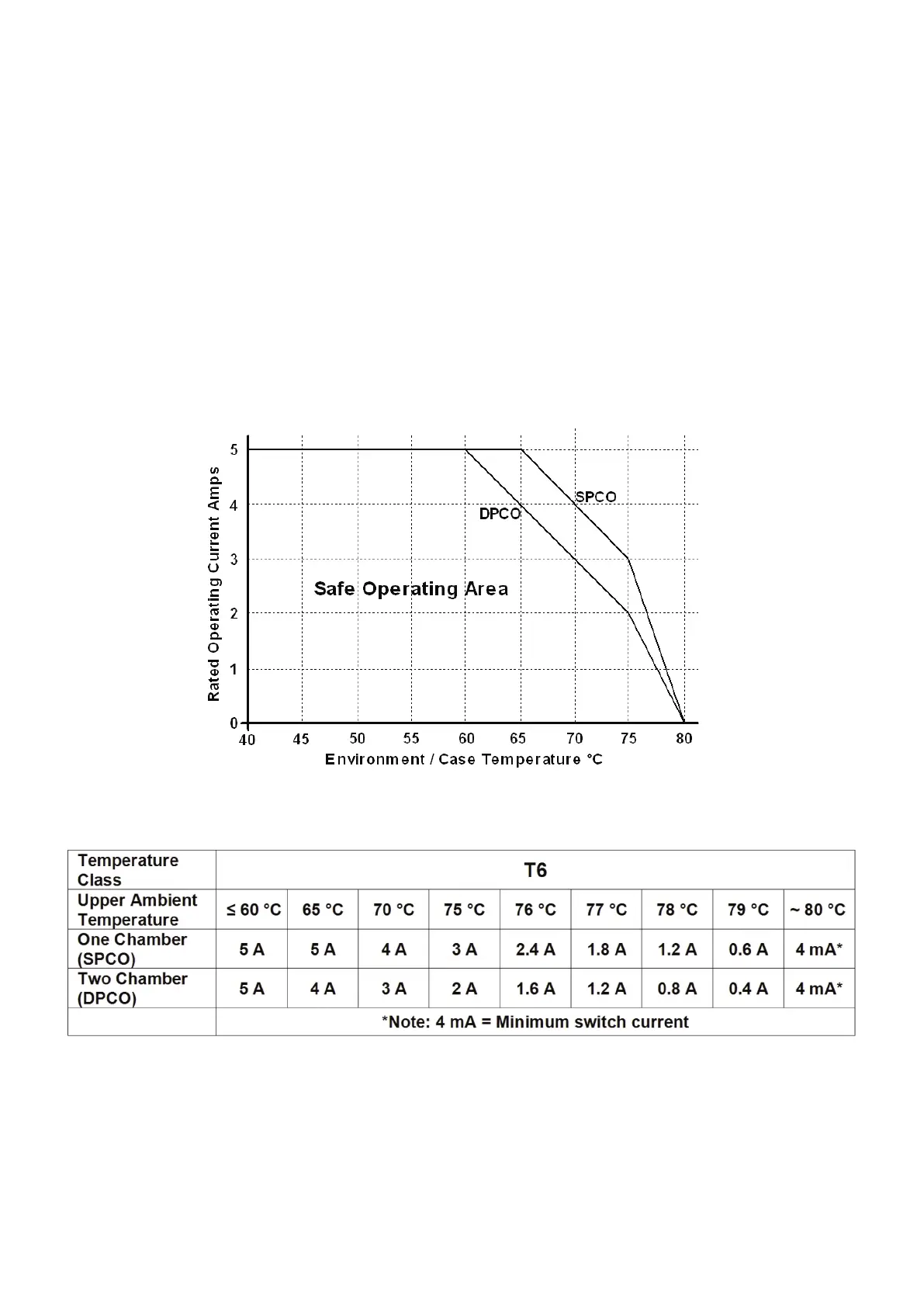
• Explanation of Tamb*: To maintain T6 temperature classification the vibration switch
maximum surface temperature due to any combination of ambient temperature and heat
from attached machinery the operating current of the vibration switch (which can cause
internal heat generation) must be limited as shown in the graph and table below;